


8-16
hsb
2
PLUS Series Color LCD Display
Radar System Tests
and Installation
Alignment
8.7 Radar System Tests and Installation Alignment
Once you have installed your Pathfinder Plus Radar System and made all the
connections, you need to check your installation and perform the System Tests
before using the system for navigation. It is strongly recommended that the
System Tests are performed before connecting the radar to other equipment in
an integrated system. If you have extended your inter-unit cable, you will also
need to check the display timing. If you encounter any problems, refer to
Chapter 9.
You may wish to read Chapters 2 to 4, and familiarise yourself with the
operation of the system, before performing the initial set up and alignment.
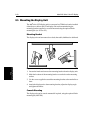
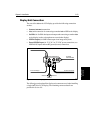
System Check
Before performing the functional test, check the following:
• All securing bolts are fully tightened and mechanical locking arrange-
ments as specified are in place.
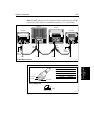
• Scanner and power connections have been made.
O n the open array scanner, set the power switch (on the pedestal) ON.
• All connecting wires are secured and protected as necessary.
Note: If you are the boat owner and have performed the installation yourself,
ask your authorised installation dealer to check the installation before going
to sea.
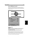
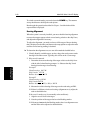
Switch On and Initial Setup
To switch on the display unit, press and hold the POWER key until the unit
beeps. Since the display is a radar master, the magnetron warm-up sequence
should start, after which the unit should enter Stand-by mode.
The display switches on in the last used mode. If it is necessary to change the
mode, press
DISPLAY to show the Display pop-up. Press DISPLAY again, as
necessary, to select Radar mode, then press
ENTER.
If necessary, adjust the lighting (see Changing the Brightness on page 2-6).
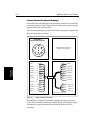
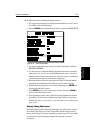
If required, change the default language settings as follows:
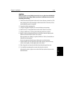
1. Press the
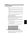
MENU key to display the setup soft keys.
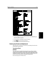
2. Press the SYSTEM SET UP soft key.
The
SYSTEM SET UP menu is displayed, listing the parameters and their cur-
rent settings. The complete list, which you can scroll down, is shown in the
following illustration.
D3640-3
SYSTEM
SET UP¬
RADAR
SET UP¬
MARPA
SET UP¬