


Chapter 3: Standard Radar Operations 3-3
Determining Actual
Radar Range
.
* The maximum range depends on your scanner type, as detailed in the Pathfinder Plus Radar
Scanner Owner’s Handbook.
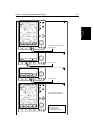
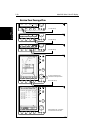
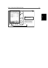
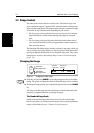
The number of range rings shown in the table is the number to the selected
range. Additional range rings are displayed to the edge of the radar picture, at
the standard ring interval for the current range, and are visible when the centre
is offset.
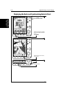
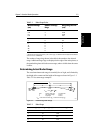
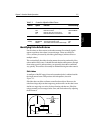
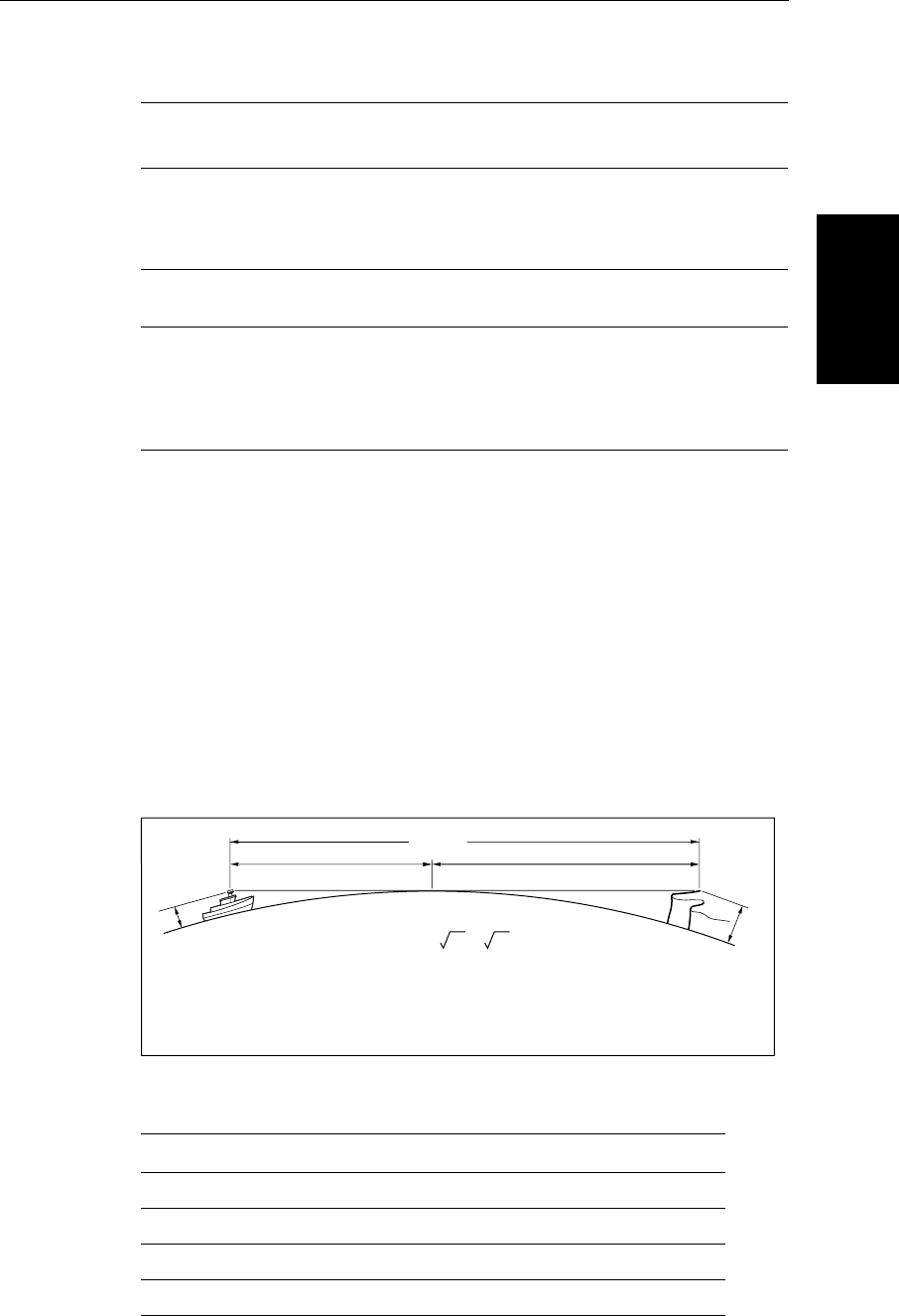
Determining Actual Radar Range
The actual maximum radar range is essentially line-of-sight, and is limited by
the height of the scanner and the height of the target as shown in Figure 3-1.
Table 3-2 lists some range examples:
Figure 3-2: Determining Radar Range
Table 3-1: Radar Range Scales
Maximum Range
(nm)
Number of Range
Rings
Range Ring Interval
(nm)
0.125
0.25
0.5
0.75
2
2
4
3
0.0625
0.125
0.125
0.25
1.5
3
6
6
0.25
0.5
6
12
24*
48*
72*
6
6
6
6
6
1
2
4
8
12
Table 3-2: Radar Range
Antenna Height (m) Target Height (m) Maximum Range (nm)
3 3 7.8
3 10 10.9
5 3 8.9
5 10 12.0
a
1
a
2
Earth
h
H
Cliff
Radar
D1643-2
R
max
R
max
= 2.23 ( h + H )
R
max
h
H
maximum radar range
radar antenna height
target height
in nautical miles
in metres
in metres
R
max
= radar horizon of antenna (
a
1
) + radar horizon of target (
a
2
)