


7
INSTALLA
TION
Connect the Speaker Wires (if external amplifiers are not used) to the corresponding speaker
leads by soldering and heat shrinking all connections for a reliable installation. If only one pair
of speakers is utilized in the system, use only the
FRONT speaker leads and heat shrink the
unused REAR leads to prevent from shorting out. Be sure to maintain speaker polarity. DO NOT
chassis ground any speaker leads as unstable operation may result.
11. Install the Preamp Output Harness (if external amplifiers will be used) by plugging the RCA
cables into the corresponding extension RCAs that feed the input of the amplifiers. Be sure to
route the signal cables away from any high current wires to prevent coupling noise from
radiated electrical fields into the audio signal. The FRONT RCAs connect to the Front speaker's
amplifier. The REAR RCAs connect to the Rear speaker's amplifier. The SUM* RCAs connect to
the Subwoofer amplifier.
12. Connect the CD Changer (optional for model 9210 only) by plugging the 8-pin DIN cable into
the connector located at the rear of the source unit.
13. Connect the Antenna by plugging the antenna cable into the connector located at the rear of the
source unit. Be sure the antenna is securely grounded to the vehicle for proper radio reception.
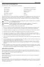
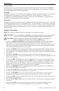
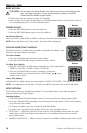
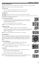
STANDARD MOUNT
Installing;
• Mount the Locks for the Installation Sleeve
onto the source unit (use supplied screws).
• Mount the Installation Sleeve into a secure
instrument panel.
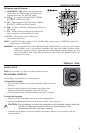
NOTE: Make sure to mount the Source Unit as
close to horizontal as possible for
optimum CD Player performance.
Mounting Angles of up to ±20˚ from
horizontal can be accommodated.
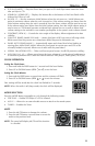
• Bend Appropriate Tabs on all sides of the
installation sleeve. See Installation Sheet.
• Install Source Unit by sliding unit into installation sleeve until it clicks into place.
• Mount Back Strap securely behind the instrument panel to prevent source unit vibration.
• Back strap Screw should be 6mm max (use supplied screw).
• Connect Antenna to antenna jack on rear of source unit.
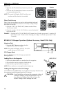
Removal;
• Disconnect Back Strap from rear of radio (if used).
• Remove Trim Piece from front of radio.
• Insert Release Keys into left and right sides of source unit to
disengage locks.
• Remove Source Unit from installation sleeve with release keys.
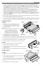
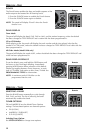
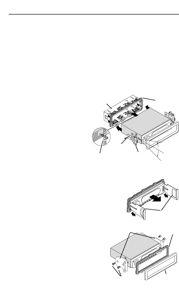
ISO-DIN MOUNT
Installing;
• Remove Trim Piece and Installation Sleeve from source
unit.
• Factory Bracket should align with two mounting holes
on each side of source unit.
• ISO Screws should be 6mm max (use supplied screws).
• Connect Antenna to antenna jack on rear of source
unit.
• Install Source Unit into instrument panel.
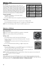
+20°
-20
°
Horizontal
Lock
Screw
Trim
Sleeve
Back Strap
Trim
Dash
Dash
Screw
Factory Bracket
Release Key