


11
SONAMP
®
875D SE 8-CHANNEL AMPLIFIER
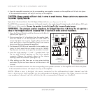
6. Press the removable connector into the corresponding zone speaker connector on the amplifier until it locks into place.
• The removable connectors will only fit one way on the amplifier.
CCAAUUTTIIOONN::
AAllwwaayyss
pprroovviiddee
ssuuffffiicciieenntt
ssllaacckk
iinn
wwiirreess
ttoo
aavvooiidd
tteennssiioonn..
AAllwwaayyss
ccoonnttaaiinn
aannyy
eexxcceessss
wwiirree
ttoo
pprreevveenntt
ttrriippppiinngg
hhaazzaarrddss..
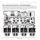
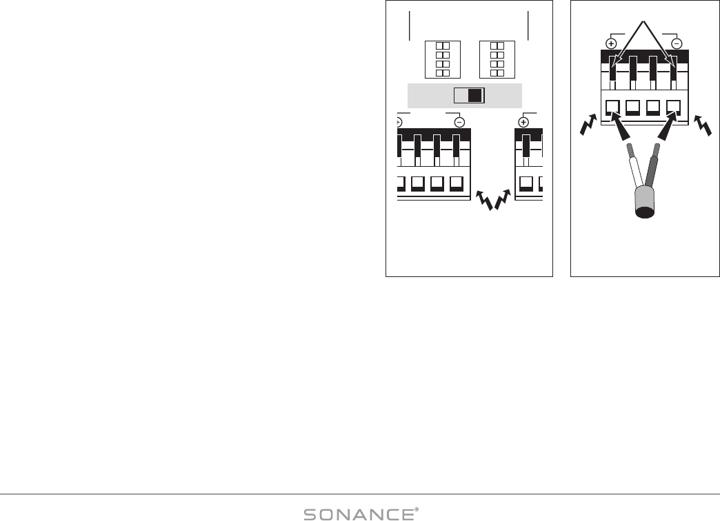
Speaker Connections for Bridged Operation (see Figures 11 & 12)
The 875D SE can operate with any pair of channels (zone) in the single-channel bridged mode, which delivers 300 watts
RMS into an 8-ohm speaker.
BBee ssuurree tthhee ssppeeaakkeerr iiss rraatteedd ttoo hhaannddllee tthhiiss iinnccrreeaasseedd oouuttppuutt ppoowweerr..
IIMMPPOORRTTAANNTT::
TThhee
mmiinniimmuumm
ssppeeaakkeerr
iimmppeeddaannccee
ffoorr
BBrriiddggeedd
OOppeerraattiioonn
iiss
88
oohhmmss..
DDoo
nnoott
ooppeerraattee
aa
zzoonnee
iinn
tthhee
BBrriiddggeedd
mmooddee
iinnttoo
aa
ssppeeaakkeerr
tthhaatt
iiss
lleessss
tthhaann
88
oohhmmss
nnoommiinnaall
iimmppeeddaannccee..
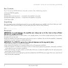
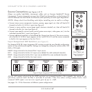
1. Move the N
ORMAL/BRIDGED switch for the zone to the BRIDGED
position (see
Figure 11
).
2. Strip no more than ¼” of insulation from the speaker leads.
Twist the strands or tin the exposed wire with solder to
ensure that there are no stray strands. (Stray strands that
touch each other or touch the amplifier chassis can cause a
short-circuit that can damage the amplifier.)
3. The Sonamp 875D SE has a removable 4-wire speaker con-
nector for each zone that can accept wire up to 14AWG.
Flip the outer two levers up to open the connector terminals.
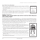
4. Insert the single speaker’s “+” and “–” speaker leads into
the two outer terminal openings on the 4-wire speaker
connector. Observe the polarity shown in the chassis
markings
above
the connector (see
Figure 12
).
5. After making sure that there are no stray wires touching
each other, flip the two levers down to lock the wires in the
terminal.
6. Press the removable connector into the corresponding zone speaker connector on the amplifier until it locks into place.
• The removable connectors will only fit one way on the amplifier.
NOTE: When a zone is bridged, the source connected to the odd-numbered input channel and the
I
NPUT
A
SSIGNMENT
DIP switches for the odd-numbered channel function. The input connected to the
even-numbered channel and the switches for the even-numbered channel are disabled.
+ 1 – – 2 +
BRIDGED
8Ω MIN
+
–
Flip Outer 2 Levers UP
Figure 12:
Bridged Speaker
Connection
ON
ON
ON
ON
OFF
OFF
OFF
OFF
ON
ON
ON
ON
OFF
OFF
OFF
OFF
DIRECT
LEFT
RIGHT
AUX
DIRECT
LEFT
RIGHT
AUX
+
1 – – 2 + + 3
–
CH1 CH2
BRIDGED
8Ω MIN
B
8
NORMAL BRIDGED
BRIDGED
Figure 11:
Zone Bridging
Switch