


14
SONAMP
®
875D SE 8-CHANNEL AMPLIFIER
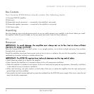
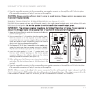
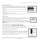
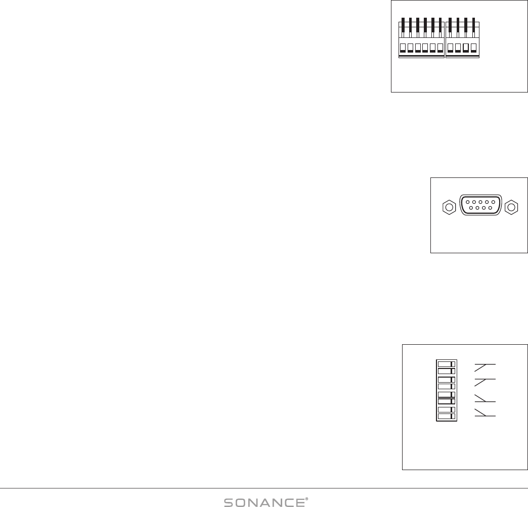
Zone Trigger Outputs
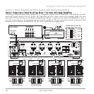
The 875D SE has individual TRIGGER OUTPUT connections for each zone that provide 12V
DC whenever the zone is ON (see
Figure 18
). This trigger can be used to control other
devices such as Sonance AL2/AS2 automatic secondary switches, other Sonamps or
12V relays.
• The current draw on each zone’s T
RIGGER OUTPUT connection should not exceed
200mA.
The T
RIGGER OUTPUT connectors feature flip-up levers similar to the ones used on the
speaker connectors:
1. Open the levers for the zone’s T
RIGGER OUTPUTS.
2. Insert the control wires into the appropriate openings in the connector (observe the correct “+” and “–” polarity).
3. Close the levers.
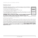
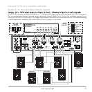
Serial Control
The 875D SE’s RS-232 Control Input (see
Figure 19
) allows many 875D SE functions to be
serial-controlled by 3rd-party control systems, and allows many of the amplifier’s performance
parameters to be monitored in real-time via the 3rd-party controller.
The 875D SE’s open architecture allows you to use it with a variety of RS-232 controllers. Specific
modules for use with Crestron
®
and AMX
®
controllers are available for download at
wwwwww..ssoonnaannccee..ccoomm
. Please check the website for information about compatibility with additional
controllers.
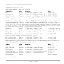
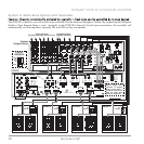
Connecting the 875D SE to a Serial Control Device
The 875D SE’s RS-232 Pinout is:
PPiinn 22:: RRXXDD;; PPiinn 33:: TTXXDD;; PPiinn 55:: GGNNDD..
Use a null modem cable to connect the 875D SE’s RS-232 C
ONTROL INPUT to a serial control device. To verify the pinout of
other serial devices, the TXD pin of an active port will show a negative DC voltage.
NOTE: To connect to a Crestron controller, use the Crestron CNSP-124
cable (available separately from Crestron).
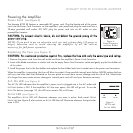
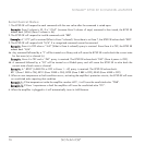
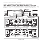
Enabling 875D SE Zone Serial Control
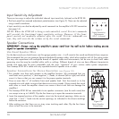
To enable serial control of of a zone, both of that zone’s AUTO and VOLT Trigger Mode
switches must be set in the ON position (see
Figure 20
). Setting a zone to
RS-232
disables
its rear-panel Auto and Voltage trigger functions — they can only be serial-controlled.
NOTE: Zones not set for RS-232 control can be polled by the control
device, but cannot be controlled by the device.
EXTERNAL TRIGGER
INPUTS 5 – 24V AC
–
ALL CH1/2 3/4 5/6 7/8
+ – + – + – + – + –
Figure 18: Zone Trigger Output
Connections
RS-232
Figure 19:
RS-232 Control Input
AUTO
VOLT
AUTO
VOLT
AUTO
VOLT
AUTO
VOLT
TRIGGER MODE
CH 1/2
CH 3/4
CH 5/6
CH 7/8
OFF ON
RS-232
RS-232
RS-232
RS-232
Figure 20:
All Four Zones set for
Serial Control