


13
SONAMP
®
875D SE 8-CHANNEL AMPLIFIER
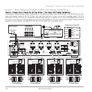
OFF (Bypass) Mode
When a zone’s A
UTO and VOLT Auto-On Trigger switches are both set in the OFF position, the A
UTO-ON circuitry is
bypassed and the amplifier’s front-panel P
OWER button will turn all zones ON and OFF simultaneously (see
Figure 2
, on
page 5).
BBE
®
Sound Enhancement
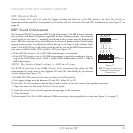
The Sonamp 875D SE incorporates BBE
®
Sound Enhancement. The BBE process improves
the presence and detail of speakers, especially at lower listening volumes, improving the
sound quality of your music — especially distributed audio systems playing background
music. BBE also restores clarity and definition (or focus) to spoken voices, which makes
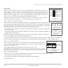
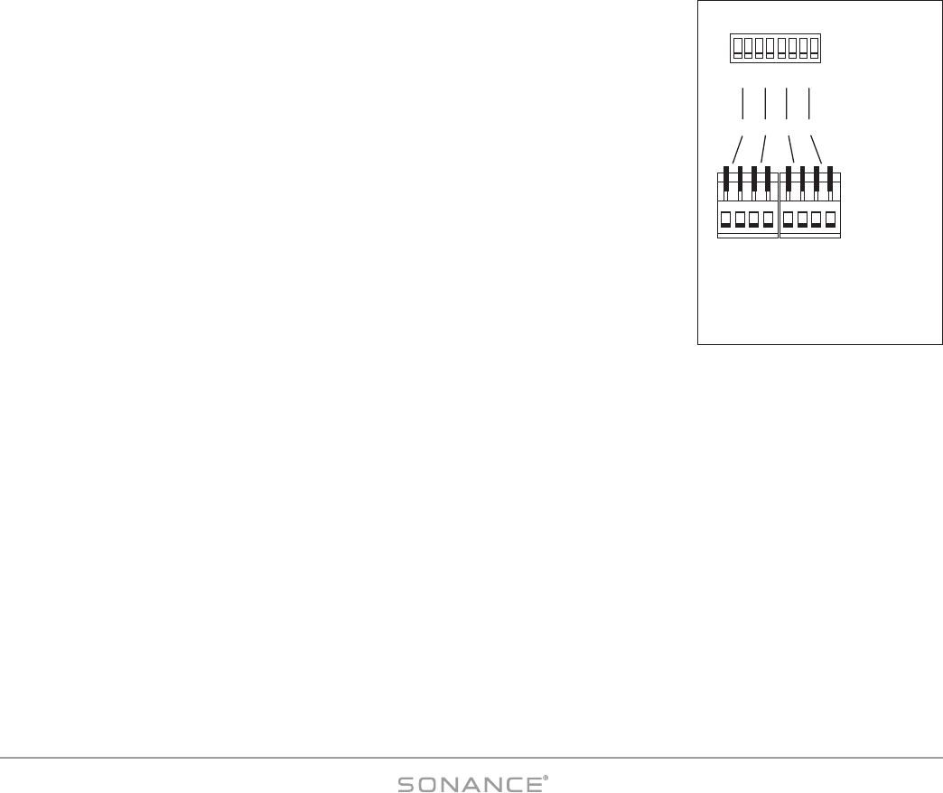
paging systems easier to understand without having to run them at high volumes. Each
zone in the 875D SE has 2 individual switches that let you set the BBE enhancement for
that zone to HIGH (+9dB), LOW (+6dB) or OFF (see
Figure 17
):
• If the OFF/ON switch is set to OFF, BBE enhancement is not applied
• If the OFF/ON switch is set to ON, BBE enhancement is applied according to the set-
ting of the LOW/HIGH switch: LOW = +6dB of BBE enhancement; HIGH = +9dB of
BBE enhancement.
NOTE: The factory-default setting is +6dB on all zones.
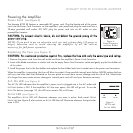
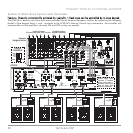
The 875D SE also has a set of BBE CONTROL INPUT connections that allow the BBE
enhancement for each zone to be triggered ON and OFF individually by an external
control voltage (see
Figure 17
):
• The BBE OFF/ON switch for the zone must be in the OFF position.
• The trigger voltage must be between 5V and 24V, either AC or DC.
The E
XTERNAL TRIGGER connectors feature flip-up levers similar to the ones used on the speaker connectors:
1. Open the levers for the zone’s E
XTERNAL TRIGGER inputs.
2. Insert the control wires into the appropriate openings in the connector.
3. Close the levers.
The front-panel Z
ONE STATUS LEDs indicate if BBE processing is being applied to a zone (see
Figure 3
, on page 7).
BBE CONTROL
BBE CONTROL
INPUTS 5 – 24V AC–DC
OFF
LOW
OFF
LOW
OFF
LOW
OFF
LOW
ON
HIGH
ON
HIGH
ON
HIGH
ON
HIGH
1/2 3/4 5/6 7/8 CH
+ – + – + – + –
Figure 17:
BBE Control Switches and
External Control Input
Connections