


12
SONAMP
®
875D SE 8-CHANNEL AMPLIFIER
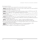
Auto-On
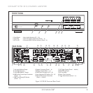
You can set your 875D SE so that any zone will automatically turn ON when it receives an
audio signal, or when it receives a control voltage from an external source (such as a
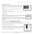
Sonance Navigator Harbor multi-zone controller). Each zone has two Trigger Mode switches
located on the rear panel: Auto — zone is turned ON when an audio signal is present, and
Volt — zone is turned ON by an external control voltage (see
Figure 14
).
NOTE: Setting both switches ON puts that zone in the Serial control mode,
disabling the Auto On feature. (See Serial Control, on page 14.)
AUTO (Audio) Trigger Mode
When a zone’s AUTO switch is set to the ON position, any audio signal arriving at the zone’s active
input connectors (as determined by the I
NPUT ASSIGNMENT DIP SWITCHES, see page 8) will activate
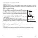
the zone for operation. The sensitivity of the zone’s A
UTO-ON circuit can be increased or decreased
by adjusting the A
UTO ON level control on the front panel (see
Figure 15
).
• Turning the control clockwise
increases
the sensitivity (
less
voltage is required to trigger the
A
UTO-ON function).
• Turning the control counter-clockwise
decreases
the sensitivity (
more
voltage is required to
trigger the A
UTO-ON function).
The A
UTO-ON trigger sensitivity ranges from 5mV/ch in the full clockwise position to OFF (AUTO-
O
N will not trigger) in the full counter-clockwise position.
In the A
UTO-O
N mode the zone will remain ON for approximately 3 minutes after the audio signal has ceased. This
provides ample time to prevent erratic operation from pauses between musical passages or while changing sources.
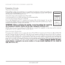
VOLTAGE Trigger Mode
When a zone’s VOLT switch is set to the ON position it can be automatically turned ON
by an external trigger voltage that appears at the zone’s E
XTERNAL TRIGGER INPUT
connections (see
Figure 16
).
• The trigger voltage must be between 5V and 24V, either AC or DC.
The 875D SE has individual E
XTERNAL TRIGGER INPUT connections for each zone, and an
additional E
XTERNAL TRIGGER INPUT connection (labeled ALL) that will turn all 4 zones ON
from a single voltage trigger.
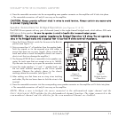
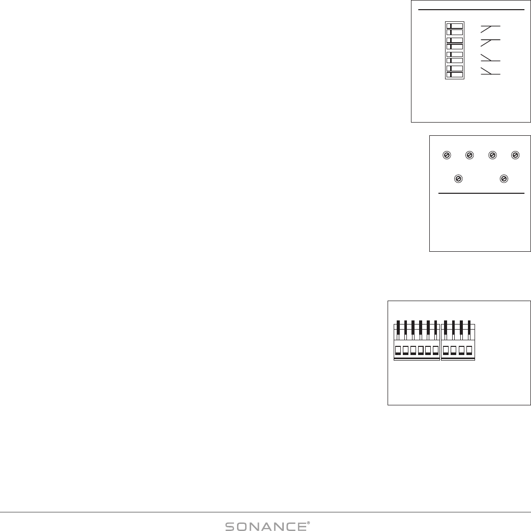
The E
XTERNAL TRIGGER connectors feature flip-up levers similar to the ones used on the speaker connectors:
1. Open the levers for the zone’s E
XTERNAL TRIGGER inputs.
2. Insert the control wires into the appropriate openings in the connector.
3. Close the levers.
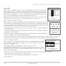
EXTERNAL TRIGGER
INPUTS 5 – 24V AC–DC
ALL CH1/2 3/4 5/6 7/8
CH
C
H
+ – + – + – + – + –
Figure 16:
External Trigger Input
Connections
AUTO
VOLT
AUTO
VOLT
AUTO
VOLT
AUTO
VOLT
TRIGGER MODE
CH 1/2
CH 3/4
CH 5/6
CH 7/8
OFF ON
RS-232
RS-232
RS-232
RS-232
Figure 14:
Auto-On Trigger Switches
AUTO ON
LRLR
3 – 4 5 – 6
Figure 15:
Zone A
UTO ON (Audio)
Trigger Sensitivity
Adjustments