


9
SONAMP
®
875D SE 8-CHANNEL AMPLIFIER
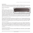
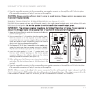
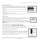
Source Connections (see
Figures 6 & 7
)
Always use quality high-fidelity interconnect cables such as Sonance MediaLinQ
®
Bronze
Interconnects. If source components are more than 20 feet from the amplifier, use the Sonance LS2
and LR2 Balanced Line-Level Sender and Receiver (sold separately) to avoid signal degradation.
NOTE: Always check local building codes before installing wire in walls or ceilings.
• Connect stereo source components (receiver, preamp, page signal, etc.) that will feed all 8
channels to the B
US
LEFT & RIGHT inputs (see
Figure 6
).
• Connect a mono auxiliary source (page signal, electronic doorbell, etc.) that will feed all 8
channels to the B
US
AUX input (see
Figure 6
).
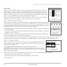
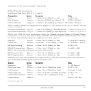
• Connect zone-specific sources (audio control system zone output, video game, etc.) into the
individual channel D
IRECT inputs (see
Figure 7
).
• Connect additional amplifiers to the buffered
Bus Outputs
(see
Figure 6
). The source connect-
ed to the B
US LEFT & RIGHT Inputs appears at the L and R OUTPUTS, and the source connected
to the B
US AUX input appears at the AUX OUTPUT.
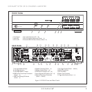
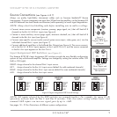
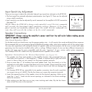
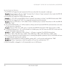
Input Assignment DIP Switches (see Figure 8)
The Sonamp 875D SE’s Input Assignment DIP switches provide the most flexible configuration
options of any multichannel amplifier. Settings are changed by setting the switches either OFF
(left) or ON (right):
DIRECT: Assign channel to the channel D
IRECT
input source.
LEFT: Assign channel to the Bus L
EFT input source (default for odd-numbered channels)
RIGHT: Assign channel to the Bus R
IGHT input source (default for even-numbered channels)
AUX: Assign channel to the Bus Aux input source
NOTE: All inputs selected by the DIP switches are summed-together. For example, for mono (L+R)
operation, activate both the Bus L and Bus R switches. Take care when setting volume levels, since
summed L&R inputs can increase signal gain by up to +6dB.
See pages 18 – 23 for illustrations of different system configurations.
ON
ON
ON
ON
OFF
OFF
OFF
OFF
ON
ON
ON
ON
OFF
OFF
OFF
OFF
DIRECT
LEFT
RIGHT
AUX
DIRECT
LEFT
RIGHT
AUX
CH1 CH2
(BRIDGED)
Figure 7:
Direct Inputs and
Input Assignment
DIP Switches
L
R
A
BUS
INPUT
OUTPUT
BUFFERED
Figure 6:
BUS Inputs &
Outputs; AUX Input
& Output
ON
ON
ON
ON
OFF
OFF
OFF
OFF
DIRECT
LEFT
RIGHT
AUX
ON
ON
ON
ON
OFF
OFF
OFF
OFF
DIRECT
LEFT
RIGHT
AUX
ON
ON
ON
ON
OFF
OFF
OFF
OFF
DIRECT
LEFT
RIGHT
AUX
ON
ON
ON
ON
OFF
OFF
OFF
OFF
DIRECT
LEFT
RIGHT
AUX
ON
ON
ON
ON
OFF
OFF
OFF
OFF
DIRECT
LEFT
RIGHT
AUX
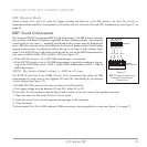
DIRECT
INPUT
LEFT BUS
INPUT
RIGHT BUS
INPUT
AUX BUS
INPUT
MONO
OPERATION
Figure 8: Input Assignment DIP Switch Settings