


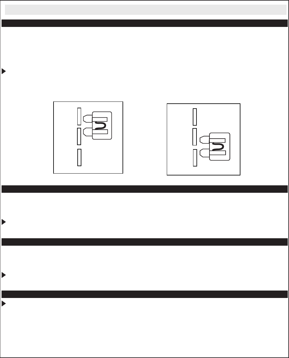
(+)
(-)
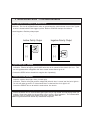
P
ositive Polarity Outp
ut
(+)
(-)
N
egative Polarity Outp
ut
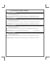
Dome Light Supervision Output (+/-) (BLACK/WHITE)
Locate the vehicle’s dome light or pin switch wire.
Verification: This wire will register positive voltage or ground when the vehicle's dome is turned ON. Typically
this wire is installed with the door trigger input wire. Refer to NEG/POS door input for reference.
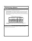
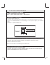
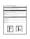
To select Negative or Positive polarity output:
Refer to Fuse Placement Diagram below.
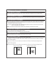
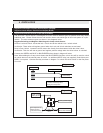
Negative Door Input (GREEN)
Locate the vehicle’s dome light or door pin switch wire.
Verification: This wire will register ground (NEG) when the door is opened and the interior light is on. This
wire will register positive voltage when the door is closed and the interior light is off.
Connect the GREEN wire to the vehicle’s negative door input wire(s).
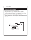
Positive Door Input (PURPLE)
Locate the vehicle’s dome light or door pin switch wire.
Verification: This wire will register positive voltage(POS) when the door is opened and the interior light is on.
This wire will register ground or "0" Volts when the door is closed and the interior light is off.
Connect the PURPLE wire to the vehicle’s negative door input wire(s).
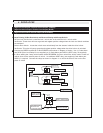
Chassis Ground Source (BLACK)
Connect the BLACK wire to a solid chassis ground point using a ring terminal and self tapping screw (not
supplied). Scrape away paint from the grounding point to ensure a good connection. The recommended
grounding point is a painted metal surface in the driver’s side kick panel area.
Note: Do not ground the BLACK wire with any other vehicle components.
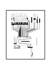
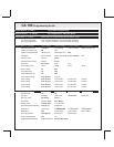
2. BASIC INSTALLATION - 22 PIN BASE HARNESS