


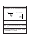

Negative Lock Output / Positive Unlock Output (GREEN)
Negative Unlock Output / Positive Lock Output (BLUE)
Negative Second Door Unlock Output (BLUE/GREEN)
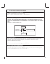
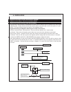
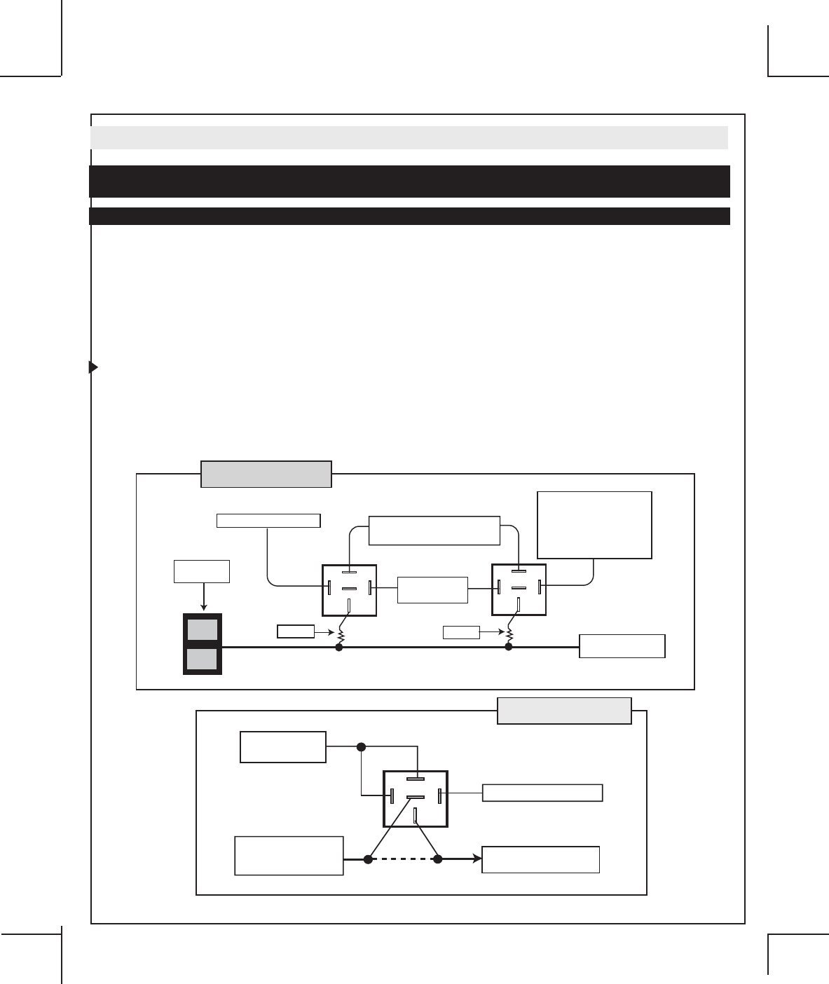
One Wire Positive Multiplexed and One Wire Multiplexed With 2-step Unlock Feature:
All Door Lock and Unlock: Locate the lock / unlock wire at the vehicle’s lock / unlock switch.
Verification: This wire will show variable positive voltage when the switch is activated. Please consult the
wire and location chart for specific resistor values for your vehicle.
Driver’s Door Unlock: Locate the unlock motor wire directly from the actuator inside the driver’s door.
Verification: This wire will rest at ground and register positive voltage when the driver’s door is unlocked.
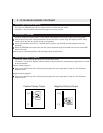
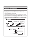
Connect the GREEN and BLUE or BLUE/GREEN wires shown in diagram 14 below. Use (1) Code Alarm
part DLRK (Door Lock Relay Kit, not included) or (2) Code Alarm part HDRLY (SPDT relay, not included).
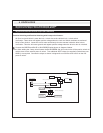
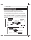
Note: When adding the 2 step unlock feature the BLUE/GREEN 2nd door unlock wire will be used to unlock all
vehicle doors on the second press of unlock. An additional SPDT relay not supplied (Code Alarm part
HDRLY) is required. Connect the relay as shown in diagram 15 to unlock the driver’s door on the first
press of unlock.
4. DOOR LOCKS
30
87
87a
86
85
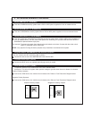
BLUE (-) Unlock Outpu
t
To Unlock Side Of
Driver's Door Actuator
Fused +12 Volt
Battery Source
From Keyless Entry
Module Or Door
Lock/Unlock Relays
CUT
X
Diagram 15
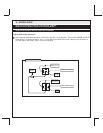
30
87
87a
86
85
Fused +12 Volt
Battery Source
Lock
Unlock
Door
Lock Switch
30
87
87a
86
85
GREEN (-) Lock Output
BLUE (-) Unlock Output
Or BLUE/GREEN (-) 2nd
Door Output When
Installing The 2-Step
Unlock Feature
Fused +12 Volt
Battery Source
Resistor
Resistor
Vehicle Door Lock
Control Relays
Diagram 14