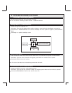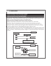
Ground When Armed Output (ORANGE)
This wire will show ground when the system is armed.
This wire is used for controlling window modules or additional sensors.
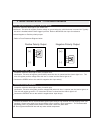
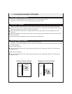
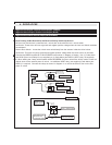
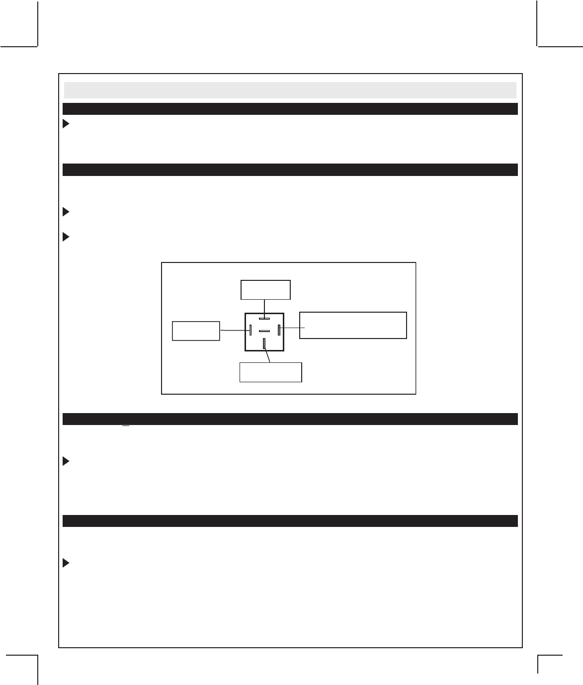
Headlight Output (LT. GREEN/ORANGE)
Locate the vehicle’s headlight wire.
Verification: This wire will register either positive voltage or ground when the headlights are turned on.
Connect the LT. GREEN/ORANGE to the vehicles headlight wire if the system is negative. (LOW CURRENT
ONLY).
Connecting to a positive headlight output.
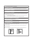
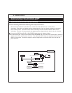
Hood Pin Input (GRAY)
Install a Hood Pin Switch and connect to the GRAY wire. This connection is required for Remote Start.
Verification: This wire when connected will register ground when the vehicle hood is opened.
Connect the GRAY wire to the hood pin.
Note: Be sure to loom the wire, and seal the grommet with 3M caulk.
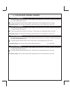
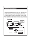
Low Current Horn Output (BROWN/BLACK)
Locate the vehicle’s horn wire at the steering column.
Verification: This wire will rest at positive voltage and register ground when the horn switch is pressed.
Connect the BROWN/BLACK wire to the vehicle’s horn wire.
2. 22 PIN BASE HARNESS CONTINUED
30
87
87a
86
85
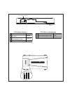
Lt. GREEN/ORANGE Headlight
Output From Control Module
To Vehicle Headlight
Wire
Fused +12 Volt
Battery Feed
Fused +12 Volt
Battery Feed


