


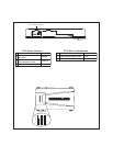
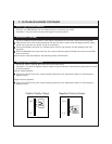
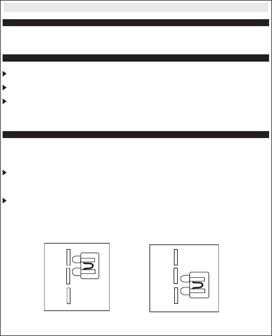
(+)
(-)
P
ositive Polarity Outp
ut
(+)
(-)
N
egative Polarity Outp
ut
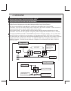
Instant Trigger Input (BLUE/WHITE)
This wire is a GROUND input for an external sensor or secondary pin switch
Verification: This wire when connected will trigger the security system
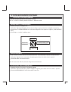
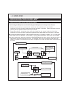
Siren Output (+) (BROWN)
Locate a suitable mounting location in the engine compartment for the siren, away from moving parts.
With the bell of the siren aiming downwards, secure the siren in place using self tapping screws, being
careful not do drill into any hoses, wiring or components.
Connect the BLACK siren wire to a chassis ground using a ring terminal and self tapping screw (not
supplied).
Route the BROWN siren output wire from the control module through the firewall and connect to the RED
wire on the siren.
Note: Be sure to loom the wire/wires, and seal the grommet with 3M caulk.
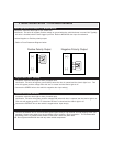
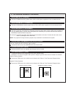
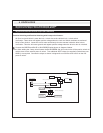
Parking Light Output (+/-) (WHITE)
Locate the vehicle’s parking light wire at the vehicle light switch
Verification: This wire will register positive voltage or ground when the vehicle parking light switch is turned
to the ON position.
Positive Polarity Systems:
Connect the WHITE wire to the vehicle’s parking light wire at the light switch. Refer to Fuse Placement
Diagram below
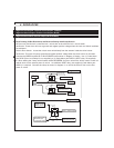
Negative Polarity Systems:
Connect the WHITE wire to the vehicle’s parking light wire at the light switch. Refer to Fuse Placement
Diagram below
2. 22 PIN BASE HARNESS CONTINUED