


Physical Considerations
2-2
Evaluation Module Layout
2.1 Physical Considerations
The EVM board has three circuit development areas. Each area can be
separated from the others by breaking along the score lines. The circuit layout
in each area supports an op amp package, voltage reference, and ancillary
devices. The op amp package is unique to each area as described in the
following paragraphs. The voltage reference and supporting devices are the
same for all areas. Surface-mount or through-hole components can be used
for all capacitors and resistors on the board.
The voltage reference can be either surface-mount or through-hole. If
surface-mount is desired, the TLV431ACDBV5 or TLV431AIDBV5 adjustable
shunt regulators can be used. If through hole is desired, the TLV431ACLP,
TLV431AILP, TL431CLP, TL431ACLP, TL431ILP, or TL431AILP adjustable
shunt regulators can be used. Refer to Texas Instruments’ Power Supply
Circuits Data Book (literature number SLVD002) for details on usage of these
shunt regulators.
Each passive component (resistor or capacitor) has a surface mount 1206
footprint with through holes at 0.2″ spacing on the outside of the 1206 pads.
C105, C106, C107, C207, C208, C209, C312, C314, and C315 have a surface
mount 1210 footprint with through holes at 0.2″ spacing on the outside of the
1210 pads. Therefore, either surface-mount or through-hole parts can be
used. The potentiometer for the offset nulling feature in area 100 can also be
either a surface-mount or a through-hole unit.
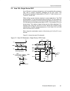
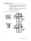
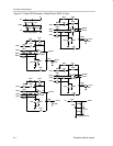
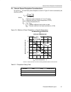
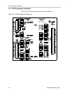
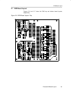
Figures 2–1 through 2–3 show schematics for each of the board areas. The
schematics show all components that the board layout can accommodate.
These should only be used as reference, since not all components will be used
at any one time.