General Power Dissipation Considerations
2-7
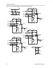
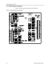
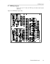
Evaluation Module Layout
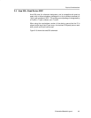
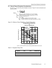
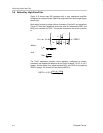
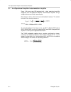
2.5 General Power Dissipation Considerations
For a given θ
JA
, the maximum power dissipation is shown in Figure 2–4 and is calculated by the
following formula:
P
D
T
MAX
–T
A
JA
Where:
P
D
= Maximum power dissipation of Txxxx IC (watts)
T
MAX
= Absolute maximum junction temperature (150°C)
T
A
= Free-air temperature (°C)
θ
JA
= θ
JC
+ θ
CA
θ
JC
= Thermal coefficient from junction to case
θ
CA
= Thermal coefficient from case to ambient air (°C/W)
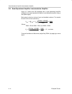
Figure 2–4. Maximum Power Dissipation vs Free-Air Temperature
2
1.5
1
0
–55 –25 5
Maximum Power Dissipation – W
MAXIMUM POWER DISSIPATION
vs
FREE-AIR TEMPERATURE
35
T
A
– Free-Air Temperature – °C
65 95 125
SOIC (16-pin)
Package
Low-K Test PCB
θ
JA
= 114.7°C/W
SOIC (8-pin)
Package
Low-K Test PCB
SOIC (14-pin)
Package
Low-K Test PCB
T
J
= 150°C
0.5
NOTE A: Results are with no air flow and using JEDEC Standard Low-K test PCB.
Table 2–1.Dissipation Rating Table
PACKAGE
θ
JC
(°C/W)
θ
JA
(°C/W)
T
A
≤ 25°C
POWER RATING
D (8) 38.3 176 710 mW
D (14) 26.9 122.3 1022 mW
D (16) 25.7 114.7 1090 mW