Two Operational Amplifier Instrumentation Amplifier
3-8
Example Circuits
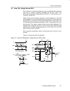
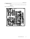
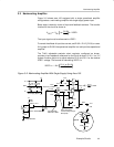
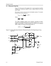
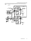
3.7 Two Operational Amplifier Instrumentation Amplifier
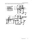
Figure 3–6 shows area 200 equipped with a dual operational amplifier
configured as a two-operational-amplifier instrumentation amplifier using a
voltage reference and single power supply.
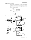
Basic setup is done by choice of input and feedback resistors. The transfer
function for the circuit as shown is:
V
OUT
V
IN
1
2R212
R220
R212
R221
VREF2
Where:
R212 = R206 and R221 = R203
To cancel the effects of input bias current, set R217 = R212 || R220 and set
R202 = R206 ||R203, or use a 0-Ω jumper for R217 and R202 if the operational
amplifier is a low input bias operational amplifier.
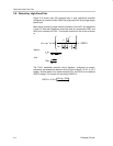
The TLV431 adjustable precision shunt regulator, configured as shown,
provides a low impedance reference for the circuit at about 1/2 V2+ in a 3 V
system. Another option is to adjust resistors R211 and R213 for the desired
VREF2 voltage. The formula for calculating VREF2 is:
VREF2 1.24 V
R211 R213
R213