


Noninverting Amplifier
3-3
Example Circuits
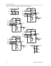
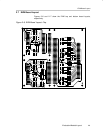
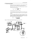
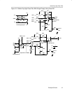
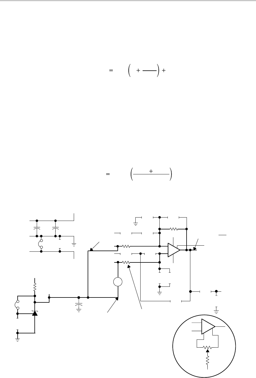
3.3 Noninverting Amplifier
Figure 3–2 shows area 100 equipped with a single operational amplifier
configured as a noninverting amplifier with single-supply power input.
Basic setup is done by choice of input and feedback resistors. The transfer
function for the circuit as shown is:
V
OUT
V
IN
1
R112
R109
VREF1
The input signal must be referenced to VREF1.
To cancel the effects of input bias current, set R102 = R112 || R109, or use a
0-Ω jumper for R102 if the operational amplifier is a low input bias operational
amplifier.
The TL431 adjustable precision shunt regulator, configured as shown,
provides a low impedance reference for the circuit at about 1/2 V1+ in a 3 V
system. Another option is to adjust resistors R113 and R111 for the desired
VREF1 voltage. The formula for calculating VREF1 is:
VREF1 1.24 V
R111 R113
R113
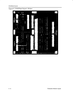
Figure 3–2. Noninverting Amplifier With Single Supply Using Area 100
C107 C108
C105
C104
V1+
V1–
V1+
GND1
V1–
Power Supply Bypass
+
–
7
6
4
3
2
V1+
V1–
R112
C109
R114
C110
R110
R109
R104
R103
R102
R105
C101
C102
1 OUT
A101+
A102–
A103+
A104–
R111
C
R
A
U102 = TLV431ACDBV5
R113
Voltage Reference
U101
V1+
VREF1 = 1.24 V
R108
+
–
V
in
Jumper
0.1 µF 10 µF
Jumper
Jumper 102 – to VREF1
V
OUT
= V
IN
R112
R109
R102 = R112 II R109,
or Short if Using Low Input
Bias Op Amp
Input Signal With
Reference to VREF1
2.2 kΩ
()
1 + + VREF4
8
SD
1 FLT
R106
C103
C106
10 µF
+
–
1
3
2
V1–
5
R101
R107
Optional
5.6 k
100 k
6