h Audio button — The Audio button has one primary function (❏) and six secondary
functions (•):
❏ Selects and deselects audio for a configuration that is being created or viewed and
lights to indicate that audio is available for configuration or viewing.
• (Audio models) Selects the Audio mode, in which you can adjust the analog input
audio level and the analog output audio volume.
• With the Enter button and RGBHV or Video button, selects between front panel
locks (Lock mode 2 and Lock mode 0).
• With the RGBHV or Video button, selects between front panel locks (Lock mode 2
and Lock mode 1).
• With the RGBHV or Video button, commands the front panel system reset.
• Selects the RS-422 protocol for the rear panel Remote port in Serial Port Selection
and Configuration mode and indicates the selection.
Power LEDs (2412 and Larger Models Only)
i Primary and Redundant Power Supply LEDs —
Green — Indicates that the associated power supply is operating within normal
tolerances.
Red — Indicates that the associated power supply is operating outside the normal
tolerances or has failed.
Button Icons
The numbered translucent covers on the input and output pushbuttons can be removed
and replaced to insert labels behind the covers.
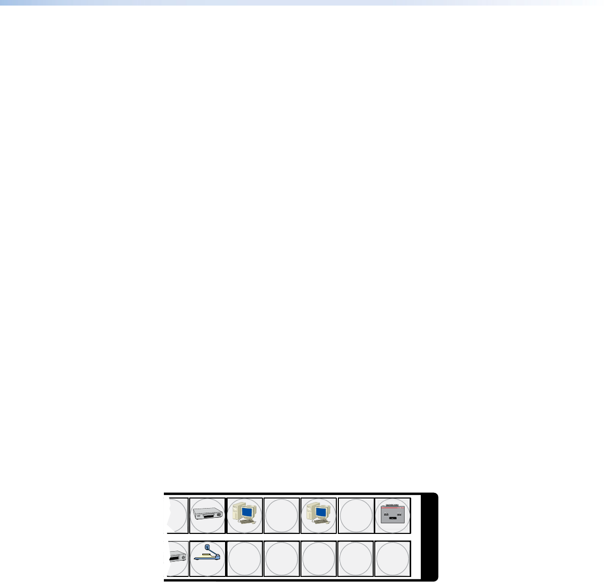
Input and output labels can be created easily with the Extron Button-Label Generator
software, which is available on the Extron web site (www.extron.com). Each input and
output can be labeled with names, alphanumeric characters, or color bitmaps for easy
and intuitive input and output selection (see figure 32). See Button-Label Generator
Program, on page 129, for details on using the labeling software. See Removing and
Installing Button Labels, on page 158, for details on using the labeling software, blank
labels you can fill in yourself, and a procedure for removing and replacing the translucent
covers.
DVD
VCR
Computer Computer
Document
Camera
VTG 200
13 15
2928 30 31 32
I
N
P
U
T
S
Figure 32. Sample Button Icons
CrossPoint and MAV Series Matrix Switchers • Operation 39


