


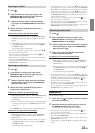

43-EN
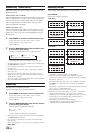
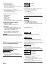
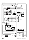
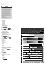
1 Amplifier Link / Vehicle Display Interface Connector
Outputs Amplifier Link / Vehicle Display Interface control
signals.
Amplifier Link:Connect this to an external Amplifier Link
compatible amplifier, using the (also separately sold)
Amplifier Link box KCE-511M.
Vehicle Display Interface:Connect this to the optional
Vehicle Display Interface box.
• Use the optional splitter cable to connect to both Amplifier Link
box KCE-511M and Vehicle Display Interface box.
•For details about connections, consult your nearest ALPINE
dealer.
2 Antenna Receptacle
3 Audio Interrupt In Lead (Pink/Black)
Connect this lead to the Audio Interface output of a cellular phone
which provides ground shorting when a call is received.
4 Remote Turn-On Lead (Blue/White)
Connect this lead to the remote turn-on lead of your
amplifier or signal processor.
5 Dimmer Lead (Orange)
This lead may be connected to the light switch of the
vehicle. This will enable the switched on vehicle's light to
dim the backlighting of the unit.
6 Switched Power Lead (Ignition) (Red)
Connect this lead to an open terminal on the vehicle’s fuse box or
another unused power source which provides (+) 12V only when
the ignition is turned on or in the accessory position.
7 Ground Lead (Black)
Connect this lead to a good chassis ground on the vehicle.
Make sure the connection is made to bare metal and is
securely fastened using the sheet metal screw provided.
8 Power Antenna Lead (Blue)
Connect this lead to the +B terminal of your power antenna,
if applicable.
• This lead should be used only for controlling the vehicle's power
antenna. Do not use this lead to turn on an amplifier or a signal
processor, etc.
9 Battery Lead (Yellow)
Connect this lead to the positive (+) post of the vehicle's battery.
! ISO Power Supply Connector
" ISO Connector (Speaker Output)
# Left Rear (+) Speaker Output Lead (Green)
$ Left Rear (–) Speaker Output Lead (Green/Black)
% Left Front (+) Speaker Output Lead (White)
& Left Front (–) Speaker Output Lead (White/Black)
( Right Front (–) Speaker Output Lead (Grey/Black)
) Right Front (+) Speaker Output Lead (Grey)
~ Right Rear (–) Speaker Output Lead (Violet/Black)
+ Right Rear (+) Speaker Output Lead (Violet)
, Ai-NET Connector
Connect this to the output or input connector of other
product (CD changer, Equalizer, iPod adapter,*
2
etc.)
equipped with Ai-NET.
*
2
If you connect to the iPod, you need the optional adapter
(KCA-420i). For details on connection, refer to the Owner's
Manual of the KCA-420i.
- Steering Remote Control Interface Connector
To steering remote control interface box.
. Fuse Holder (10A)
/ Rear Output RCA Connectors
RED is right and WHITE is left.
: Front Output RCA Connectors
RED is right and WHITE is left.
; Subwoofer Output RCA Connectors
RED is right and WHITE is left.
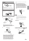
< Setting the 3WAY/2WAY switch
Set the 3way/2way Switch according to your audio system.
= System Switch
When connecting a processor using Ai-NET, place this
switch in the EQ/DIV position. When no device is
connected, leave the switch in the NORM position.
• Be sure to turn the power off to the unit before changing the switch
position.
> Power Supply Connector
? Ai-NET Cable (Included with CD Changer)
@ RCA Extension Cable (Sold Separately)
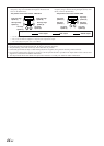
[ DC/DC Converter (CDA-9855R only).
• Do not install the converter at a location subjected to water such
as under the floor mat or air conditioner. This may cause a
malfunction.
• Do not bundle the DC/DC converter cable with other audio cables.
Doing so may induce noise into your system.
•Keep the DC/DC converter away from the Antenna cables and the
rear side of the unit, otherwise noise may be generated when
receiving radio broadcast.
\ ISO/JASO Antenna Adaptor (Sold Separately)
An ISO/JASO antenna adapter may be required, depending
on the vehicle.
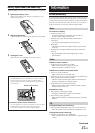
Continued