


1-10 (No.MA063)
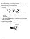
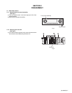
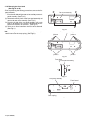
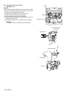
3.1.6 Removing the CD mechanism assembly
(See Fig.10)
• Prior to performing the following procedures, remove the front
panel assembly, heat sink and top chassis assembly.
Reference:
Remove the mechanism control board as required.
(1) From the inside of the top chassis assembly, remove the
three screws G attaching the CD mechanism assembly.
(2) Take out the CD mechanism assembly from the top chas-
sis.
Fig.10
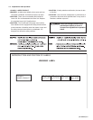
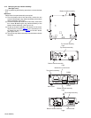
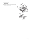
3.1.7 Removing the main board
(See Figs.11 and 12)
• Prior to performing the following procedures, remove the front
panel assembly, heat sink and top chassis assembly.
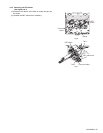
(1) From the rear side of the bottom chassis assembly, remove
the two screws H attaching the rear bracket to the bottom
chassis assembly. (See Fig.11.)
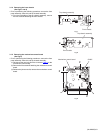
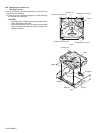
(2) From the top side of the bottom chassis assembly, remove
the two screws J attaching the main board to the bottom
chassis assembly. (See Fig.12.)
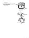
(3) Release the stopper of the connector CN701
on the main
board in an upward direction, disconnect the card wire from
the connector CN701
. (See Fig.12.)
(4) Disconnect the wire from the connector of the gear bracket
unit. (See Fig.12.)
(5) Disconnect the wire from the connector CN951
on the main
board. (See Fig.12.)
Reference:
After connecting the wires, fix the wires with the wire
holders.
(6) Take out the main board from the bottom chassis assem-
bly.
Fig.11
Fig.12
Top chassis
G
G
G
CD mechanism assembly
Rear bracket
H
Bottom chassis assembly
Connector
Wire holders
CN701
Stopper
Bottom chassis assembly
J
J
CN951
Wires
Main board
Card wire
Gear bracket unit