


1-24 (No.MA063)
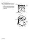
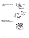
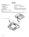
3.2.15 Removing the loading roller assembly
(See Figs.31 to 33)
• Prior to performing the following procedure, remove the
clamper assembly and top plate assembly.
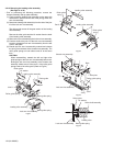
(1) Push inward the loading roller assembly on the gear side
and detach it upward from the slot of the joint g' of the lock
arm rivet assembly.
(2) Detach the loading roller assembly from the slot of the joint
h' of the lock arm rivet assembly.
The roller guide comes off the gear section of the loading
roller assembly.
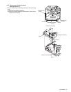
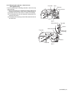
Remove the roller guide and the HL washer from the shaft
of the loading roller assembly.
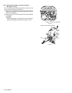
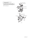
(3) Remove the screw J attaching the lock arm rivet assembly.
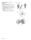
(4) Push the shaft at the joint i' of the lock arm rivet assembly
inward to release the lock arm rivet assembly from the slot
of the L side plate.
(5) Extend the lock arm rivet assembly outward and release
the joint j' from the boss of the chassis rivet assembly. The
roller guide springs on both sides come off at the same
time.
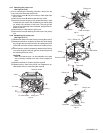
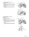
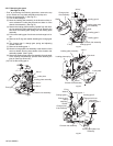
CAUTION:
When reassembling, reattach the left and right roller
guide springs to the lock arm rivet assembly before reat-
taching the lock arm rivet assembly to the chassis rivet
assembly. Make sure to fit the part k' of the roller guide
spring inside of the roller guide. (Refer to Fig.34.)
Fig.31
Fig.32
Fig.33
Fig.34
Roller guide
Roller guide spring
Roller guide spring
Roller guide spring
Roller guide
HL washer
Loading roller assembly
Loading roller assembly
Joint h'
Joint g'
Lock arm rivet assembly
Roller guide
spring
Roller guide
spring
Loading roller assembly
Loading roller assembly
Part k'
Roller guide spring
Boss
L side plate
Joint i'
Joint j'
Lock arm rivet assembly
J
Chassis rivet assembly
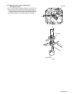
Roller guide
HL washer
Lock arm rivet assembly
Roller guide spring
Loading roller
Roller shaft assembly