


1-8 (No.MA063)
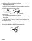
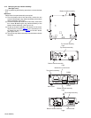
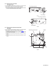
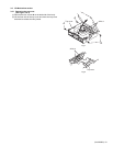
3.1.3 Removing the top chassis assembly
(See Figs.3 to 6)
• Prior to performing the following procedures, remove the heat
sink.
Reference:
Remove the front panel assembly as required.
(1) From the bottom side of the main body, remove the two
screws C attaching the top chassis assembly to the bottom
chassis assembly. (See Fig.3.)
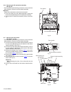
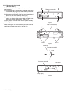
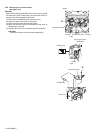
(2) From the both and rear sides of the main body, remove the
four screws D attaching the top chassis assembly to the
bottom chassis assembly. (See Figs.4 to 6.)
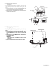
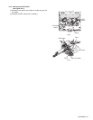
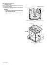
(3) Lift the top chassis assembly in the direction of the arrow,
disconnect the connector CN501
on the mechanism con-
trol board from the connector CN702 on the main board.
(See Figs.5 and 6.)
(4) Take out the top chassis assembly from the bottom chassis
assembly.
Fig.3
Fig.4
Fig.5
Fig.6
Top chassis assembly
C
C
Bottom chassis assembly
Bottom chassis assembly
Top chassis assembly
D
Top chassis assembly
D
Bottom chassis assembly
Mechanism control board
Main board
CN702
CN501
Top chassis assembly
Bottom chassis assembly
Rear bracket
D
D