


3
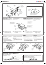
Twist the core wires when connecting.
????
???
?????
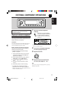
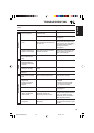
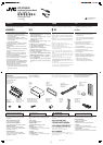
Connecting the leads / !"# /
==
==
=
/ µËÕ“¬µ–°—Ë«
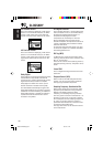
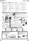
• When using the optional stay
Sleeve
!
ª≈Õ°ÀÿÈ¡
Dashboard
!
ºßÀπÈ“ª—∑¡Ï
Fire wall
ºπ—ß°—π‰ø
Washer
ª√–‡°Áπ«ß·À«π
Stay (option)
!"
=E=F
µ—«¬÷¥ (‡≈◊Õ°‰¥È)
Lock nut
!
!=
πÕµ≈ÁÕ§
Mounting bolt
!
=
≈—°µ‘¥
Screw (option)
!"#$%
=E=F
°√Ÿ (‡≈◊Õ°‰¥È)
•
==
==
=
==
==
=
==
==
=
! !
! !
!
==
==
=
• !"#
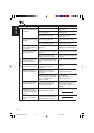
* Not included with this unit.
* !"#$
* = = !=
*
‰¡Ë√«¡°—∫™ÿ¥ª√–°Õ∫π’È
Bracket*
*
*
·∑Ëπ√Õß√—∫*
Pocket
°–‡ª“–
Bracket*
*
*
·∑Ëπ√Õß√—∫*
Flat type screws—M5 x 8 mm *
!"EM5 x 8 mmF*
= EM5 x 8 mmF*
°√ŸÀ—«‡√’¬∫ (M5 x 8 ¡‘≈≈‘‡¡µ√)*
Flat type screws—M5 x 8 mm *
!"EM5 x 8 mmF*
= EM5 x 8 mmF *
°√ŸÀ—«‡√’¬∫ (M5 x 8 ¡‘≈≈‘‡¡µ√)*
Note : When installing the unit on the
mounting bracket, make sure to use
the 8 mm long screws. If longer
screws are used, they could damage
the unit.
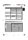
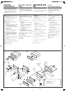
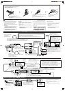
• When installing the unit without
using the sleeve
In a Toyota for example, first remove the car
radio and install the unit in its place.
Removing the unit
• Before removing the unit, release the rear
section.
1
Remove the control panel.
2
Remove the trim plate.
3
Insert the 2 handles into the slots, as
shown. Then, while gently pulling the
handles away from each other, slide out the
unit. (Be sure to keep the handles after
installing it.)
Install the unit at an angle of less than 30˚.
!"#$% 30° !
30˚= = = = !"K
µ‘¥µ—Èß™ÿ¥ª√–°Õ∫∑’Ë¡ÿ¡µË”°«Ë“ 30 Õß»“
Less than 30˚
30°
30˚=
πÈÕ¬°«Ë“ 30 Õß»“
• ‡¡◊ËÕ„™Èµ—«¬÷¥·∫∫‡≈◊Õ°‰¥È
• !"#$%&'($
!"TOYOTA !"#$% !"#$%&
!"#$%&'()*
•
! !
! !
!
==
==
=
! !
! !
!
==
==
=
==
==
=
==
==
=
==
==
=
== !"#= = !=
== == = !"K
• ‡¡◊ËÕµ‘¥µ—Èß™ÿ¥ª√–°Õ∫‚¥¬‰¡Ë„™Èª≈Õ°ÀÿÈ¡
µ—«Õ¬Ë“߇™Ëπ „π√∂¬πµÏ‚µ‚¬µÈ“
„ÀÈ∂Õ¥«‘∑¬ÿµ‘¥√∂¬πµÏÕÕ°°ËÕπ·≈–µ‘¥µ—Èß™ÿ¥ª√–
°Õ∫π’ȇ¢È“‰ª·∑π
: !"#$%&'()*+,
8 mm= !"#$%&' !
!"#$%
À¡“¬‡Àµÿ: ‡¡◊ËÕµ‘¥µ—Èß™ÿ¥ª√–°Õ∫≈ß„π·∑Ëπ√Õß√—∫‰«È
„ÀÈ„™È°√Ÿ¬“«¢π“¥
8 ¡‘≈≈‘‡¡µ√
∂È“„™È°√Ÿ¬“«°«Ë“π’ÈÕ“®∑”„ÀÈ™ÿ¥ª√–°Õ∫‡’¬À“¬‰¥ô
WW
WW
WW= != = ==
=8 mm= = = !"
K= =8 mm== =
= = == !K
!
• !"#$%&!"'()*+,-.(/
1
!"#$
2
!"#
3
!"#$%&'()*+,-."/
!"#$%&'#()*+,-./
!"#$%&'()*+,
==
==
=
• = !== != !"K
1
!= !"K
2
= !"= !"K
3
==== != =
K==== = !"
= != != = =
K=
EE
EE
E
==
==
=
==
==
=
! !
! !
!
==
==
=
==
==
=
! !
! !
!
KFKF
KFKF
KF
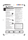
CAUTION / /
/ ¢ÈÕ§«√√–«—ß
• To prevent short-circuit, cover the terminals of the UNUSED leads with insulating tape.
• !"#$%&'()*+,-.'!/0123
• = != = !== = == != !"K
•
°“√ªÈÕß°—π°“√≈—¥«ß®√ ®–µÈÕßæ—π¢—È«“¬µ–°—Ë«∑’ˉ¡Ë„™È·≈È«¥È«¬‡∑ªæ—𓬉ø
Solder the core wires to connect them
securely.
!"#$%&'()
= != != !"
!"K
‡™◊ËÕ¡∫—¥°√’‡Èπ≈«¥·°π∑—ÈßÀ¡¥‡¢È“¥È«¬°—π
‡æ◊ËÕ§«“¡ª≈Õ¥¿—¬„π°“√„™Èß“π
31
Trim plate
= !
·ºËπ‚≈À–¢Õ∫·µËß
Control panel
!
ÀπÈ“ª—¥
Handle
!"
§—π∫—ߧ—∫
2
°“√∂Õ¥™ÿ¥ª√–°Õ∫
• °ËÕπ®–∂Õ¥™ÿ¥ª√–°Õ∫ „ÀȪ≈¥ÀπÈ“µ—¥Ë«π∑È“¬°ËÕπ
1
∂Õ¥·ºß§«∫§ÿ¡
2
∂Õ¥·ºËπ‚≈À–¢Õ∫·µËß
3
„˧—π∫—ߧ—∫ 2 Õ —π≈ß„π√ËÕß”À√—∫„™Èæ—π≈«¥ ¥—ß¿“æ ®“°π—Èπ
„Àȇ≈◊ËÕπ™ÿ¥ª√–°Õ∫ÕÕ° „π¢≥–∑’˧ËÕ¬ Ê ¥÷ߧ—π∫—ߧ—∫∑—ÈßÕß
Õ—πÕÕ°®“°°—π (¥Ÿ„ÀÈ¥’«Ë“§—π∫—ߧ—∫∑—ÈßÕßÕ—πÕ¬ŸË„πµ”·Àπ Ëß∑’ˇÀ¡“–
¡À≈—ß®“°µ‘¥µ—Èß·≈È«)
Twist the core wires when connecting.
!"#$%
=== = !"K
∫‘¥‡Èπ≈«¥·°π‡æ◊ËÕ‡™◊ËÕ¡µËÕ
Install_DV5000-1[U]/3 20/5/03, 9:20 AM3