


90
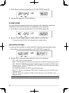
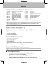
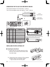
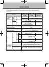
CONNECTING THE PG-5G/ PG-5H INTERFACE CABLES
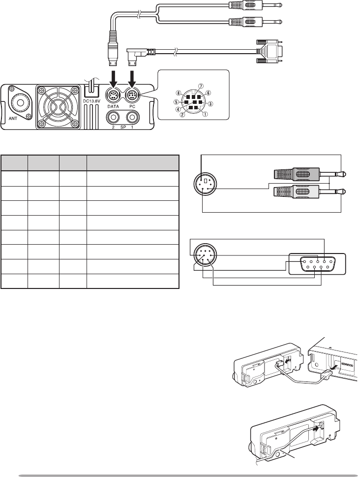
The PG-5G package comes with cable w (below).
The PG-5H packages comes with cables q and w (below).
q Data communications cable
w Serial communications cable
To PC
audio terminal
To PC 9-pin
D-SUB terminal
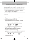
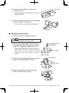
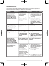
INSTALLING THE DFK-3D PANEL KIT
n Installing the Sub-Panel
1 Detach the front operation panel from the
base unit, then remove the modular cable
from both sides.
2 Connect the 4-pin connector of the supplied
modular cable to the operation panel.
• Align the cable with the cable guide.
cable guide
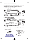
PC terminal
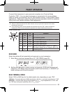
PC terminal pins:
No. Name I/O Function
q
RTS O
Request to Send
w
CTS I
Clear to Send
e
TXD O
Transmit Data
r
GND —
GND
t
RXD I
Receive Data
y
NC —
—
u
NC —
—
i
NC —
—
• For DATA terminal, refer to page 83.
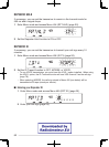
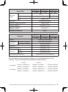
Data communications cable pin configuration
Serial communications cable pin configuration
Pink: To microphone input terminal
Green: To line out terminal