


200VW8 LCD
Safety Instruction, Warnings and Notes
21
Safety instruction, warnings and notes
index of this chapter:
1 Safety Instructions
2 Warnings
3 Notes
1 Safety Instructions
Safety regulations require that during a repair:
a. Connect the set to the AC Power via an isolation transformer
(> 800 VA).
b. Replace safety components, indicated by the symbol ,
only by components identical to the original ones. Any other
component substitution (other than original type) may
increase risk of fire or electrical shock hazard.
Safety regulations require that after a repair, the set must be
returned in its original condition. Pay in particular attention to
the following points:
a. Route the wire trees correctly and fix them with the mounted
cable clamps.
b. Check the insulation of the AC Power lead for external
damage.
c. Check the strain relief of the AC Power cord for proper
function.
d. Check the electrical DC resistance between the AC Power
plug and the secondary side (only for sets which have a AC
Power isolated power supply):
* Unplug the AC Power cord and connect a wire between the
two pins of the AC Power plug.
* Set the AC Power switch to the "on" position (keep the AC
Power cord unplugged!).
* Measure the resistance value between the pins of the AC
Power plug and the metal shielding of the tuner or the aerial
connection on the set. The reading should be between 4.5
Mohm and 12 Mohm.
* Switch "off" the set, and remove the wire between the two
Pins of the AC Power plug.
e. Check the cabinet for defects, to avoid touching of any inner
parts by the customer.
2 Warnings
a. All ICs and many other semiconductors are susceptible to
electrostatic discharges (ESD ). Careless handling during
repair can reduce life drastically. Make sure that, during
repair,
you are connected with the same potential as the mass of the
set by a wristband with resistance. Keep components and
tools also at this same potential.
b. Be careful during measurements in the high voltage section.
c. Never replace modules or other components while the unit
is switched "on".
d. When you align the set, use plastic rather than metal tools.
This will prevent any short circuits and the danger of a circuit
becoming unstable.
3 Notes
3.1 General
Measure the voltages and waveforms with regard to the
chassis ground or hot ground, depending on the tested area of
circuitry. The voltages and waveforms shown in the diagrams
are indicative.
The semiconductors indicated in the circuit diagram and in the
parts lists, are interchangeable per position with the
semiconductors in the unit, irrespective of the type indication on
3.2 Schematic Notes
All resistor values are in ohms and the value multiplier is often
used to indicate the decimal point location (e.g. 2K2 indicates
2.2 Kohm).
Resistor values with no multiplier may be indicated with either
an "E" or an "R" (e.g. 220E or 220R indicates 220 ohm).
All capacitor values are given in micro-farads ( X10 ),
nano-farads (n= X10 ), or pico-farads (p= X10 ).
Capacitor values may also use the value multiplier as the
decimal point indication (e.g. 2p2 indicates 2.2 pF).
An "asterisk" (*) indicates component usage varies. Refer to the
diversity tables for the correct values.
The correct component values are listed in the Electrical
Replacement Parts List. Therefore, always check this list when
there is any doubt.
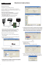
3.3 Lead Free Solder
Philips CE is going to produce lead-free sets (PBF) from
1.1.2005 onwards.
Lead-free sets will be indicated by the PHILIPS-lead-free logo
on the Printed Wiring Boards (PWB):
This sign normally has a diameter of 6 mm, but if there is less
space on a board also 3 mm is possible.
In case of doubt wether the board is lead-free or not (or with
mixed technologies), you can use the following method:
* Always use the highest temperature to solder, when using
SAC305 (see also instructions below).
* De-solder thoroughly (clean solder joints to avoid mix of
two alloys).
: For BGA-ICs, you must use the correct temperature
profile, which is coupled to the 12NC. For an overview of these
profiles, visit the website
You will find this and more technical information within the
"Magazine", chapter "Workshop information".
For additional questions please contact your local repair desk.
Due to lead-free technology some rules have to be respected
by the workshop during a repair:
Use only lead-free soldering tin Philips SAC305 with order code
0622 149 00106. If lead-free solder paste is required, please
contact the manufacturer of your soldering equipment.
In general, use of solder paste within workshops should be
avoided because paste is not easy to store and to handle.
Use only adequate solder tools applicable for lead-free
soldering tin. The solder tool must be able
- To reach at least a solder-tip temperature of 400 degree C.
- To stabilise the adjusted temperature at the solder-tip.
- To exchange solder-tips for different applications.
-6
-9 -12
Caution
http://www.atyourservice.ce.philips.com/