


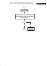
Safety Check Process
Safety Checks
After the original service problem has been corrected, a complete safety check
should be made. Be sure to check over the entire set, not just the areas where
you have worked. Some previous service may have left an unsafe condition,
which could be unknowingly passed on to your customer. Be sure to check all
of the following:
Fire and Shock Hazard
1. Be sure all components are positioned in such a way as to avoid the
possibility of adjacent component shorts. This is especially important on those
chassis which are transported to and form the service shop.
2. Never release a repaired unit unless all protective devices such as
insulators, barries, covers, strain reliefs, and other hardware have been
installed in accordance with the original design.
3. Soldering and wiring must be inspected to locate possible cold solder joints,
solder splashes, sharp solder points, frayed leads, pinched leads, or damaged
insulation(including the accord). Be certain to remove loose solder balls and all
other loose foreign particles.
4. Check across-the-line components and other components for physical
evidence of damage or deteriortion and replace if necessary. Follow original
layout, lead length and dress.
5. No lead or component should touch a receiving tube or a resistor rated at
1watt or more. Lead tension around protruding metal surfaces or edges must
be avoided.
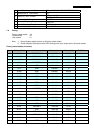
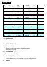
6. Critical components having special safety characteristics are identified with
ans bythe Ref.No in the parts list and enclosed within a broken line *( Where
several critical components are grouped in one area) along with the safety
symbols on the schematic diagrams and/or exploded views.
7.When servicing any unit, always use a separate isolation transformer for the
chassis failure to use a separate isolation transformer may expose you to
possible shock hazard, and may cause damage to servicing instruments.
8. Many electronic products use a polarized ac line cord(one wide pin on the
plug). Defeating this safety feature may create a potential hazard to the
service and the user. Extension cords which do not incorporate the polarizing
feature should never be used.
9. After reassembly of the unit, always perform an leakage test or resistance
test from the line cord to all exposed metal parts of the cabinets. Also check all
metal control shafts(with knobs removed), antenna terminals, handles, screws,
etc. To be sure the unit may be safety operated without danger of electrical
shock.
* Broken line
Implosion
1. All picture tubes used in current model receivers are equipped with an
intergral implosion system care should always be used, and safety glasses
worn, whenever handling any picture tube. Avoid scratching or other wise
damaging the picture tube during installation.
2. Use only replacement tubes specified by the manufacturer.
X-radiation
1. Be sure procedures and instructions to all your service personal cover the
subject of X-radiation. Potential sources of X-rays in TV receivers are the
picture tube and the high voltage circuits. The basic precaution which must be
exercised is to keep the high voltage at the factory recommended level.
2. To avoid possible exposure to X-radiation and electrical shock, only the
manufacturer’s specified anode connectors must be used.
3. It is essential that the service technician has an accurate HV meter available
at all times. The calibration of this meter should be checked periodically against
a reference standard.
4. When the HV circuitry isoperating properly there is no possibility of an X-
radiation problem. High voltage should always be kept at the manufacture,
rated value-no higher- for optimum performance. Every time a color set is
serviced, the brightness should be run up and while monitoring the HV with a
meter to be certain that the HV is requation correctly and does not exceed the
specified value. We suggest that you and your technicians review test
procedures so that HV requation are always checked as a standard servicing
procedure, and the reason for this prudent routine is cleanly understood by
everyone. It is important ot use an accurate and reliable HV meter. It is
recommended that the HV recorded on each customer’s invoice, which will
demonstrate a proper concern for the customer’s safety.
5. When troubleshooting and making test measurements in a receiver with a
problem of excessive high voltage, reduce the line voltage by means of a variac
to bring the HV into acceptable limits while troubleshooting. Do not operate the
chassis loner than necessary to locate the cause of the excessive HV.
6. New picture tubes are specifically designed to withstand higher operating
voltages without creating undesirable X-radiation. It is strongly recommended
that any shop test fixture which is to be used with the new higher voltage
chassis be equipped with one of the new type tubes designed for this service.
Addition of a permanently connected HV meter to the shop test fixture is
advisable. The CRT types used in these new sets should never be replaced
with any other types, as this may result in excessive X-radiation.
7. It is essential to use the specified picture tube to avoid a possible X-radiation
problem.
8. Most TV receivers contain come types of emergency” Hold Down” circuit to
prevent HV from rising to excessive levels in the presence of a failure mode.
These various circuits should be understood by all technicians servicing them,
especially since many hold down circuits are inoperative as long as the
receiver performs normally.
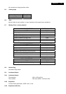
Leakage Current Cold Check
1. Unplug the ac line cord and connect a jumper between the two prongs of the
plug.
2. Turn on the power switch.
3. Measure the resistance value between the jumpered ac plug and all exposed
cabinet parts of the receiver, such as screw heads, antennas, and control
shafts. When the exposed metallic part has a return path to the chassis, the
reading should be between 1 megohm and 5.2 megohms. When the exposed
metal does not have a return path to the chassis, the reading must be infinity.
Remove the jumper from the ac line cord.
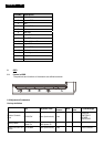
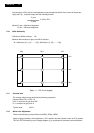
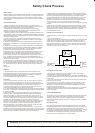
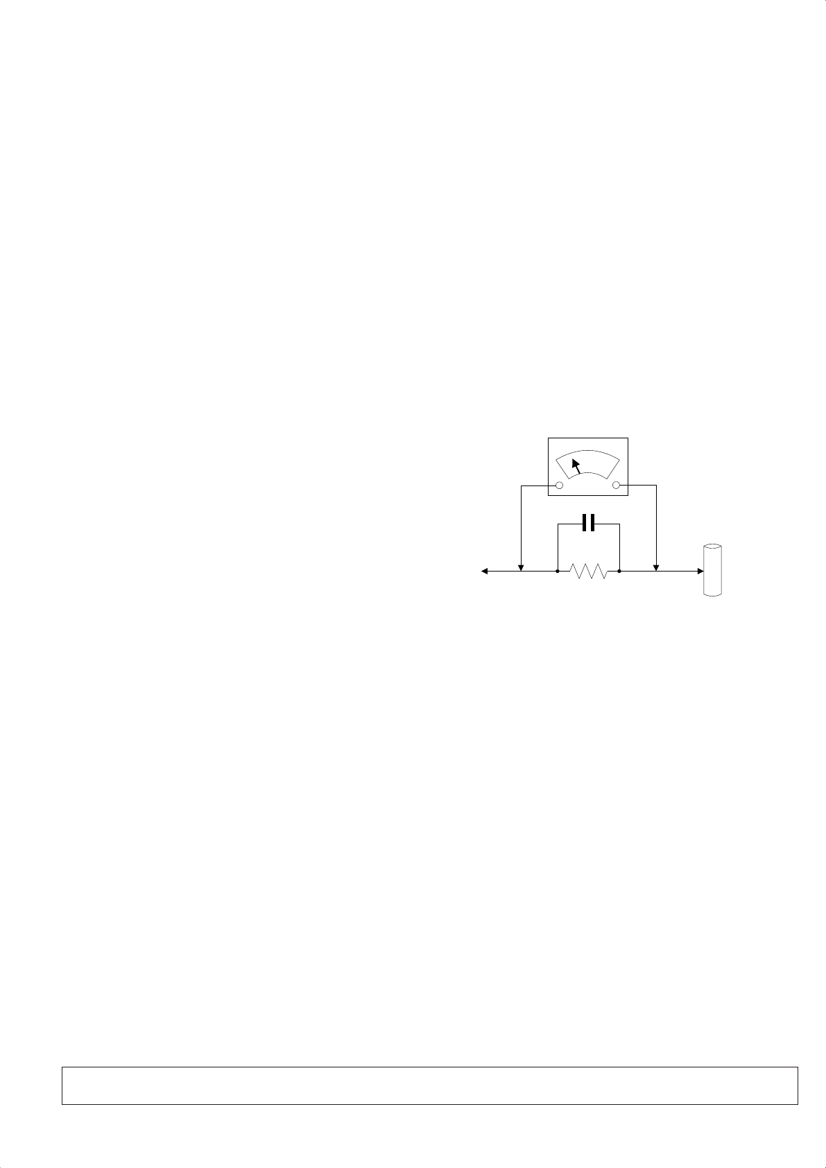
Leakage Current Hot Check
1. Do not use an isolation transformer for this test. Plug the completely
reassembled receiver directly into the ac outlet.
2. Connect a 1.5k, 10w resistor paralleled by a 0.15uf capacitor between each
exposed metallic cabinet part and a good earth ground such as a water pipe, as
shown above.
3. Use an ac voltmeter with at least 5000 ohms volt sensitivity to measure the
potential across the resistor.
4. The potential at any point should not exceed 0.75 volts. A leakage current
tester may be used to make this test; leakage current must not exceed a
possibility of shock hazard. The receiver should be repaired and rechecked
before returning it to the customer.
5. Repeat the above procedure with the ac plug reversed.(note: an ac adapter
is necessary when a polarized plug is used. Do not defeat the polarizing
feature of the plug.)
Picture Tube Replacement
The primary source of X-radiation in this television receiver is the picture tube.
The picture tube utilized in this chassis is specially constructed to limit X-
radiation emissions. For continued X-radiation protection, the replacement
tube must be the same types as the original, including suffix letter, or a Philips
approved tube.
Parts Replacement
Many electrical and mechanical parts in Philips television sets have special
safety related characteristics. These characteristics are often not evident from
visual inspection nor can the protection afforded by them necessarily be
obtained by using replacement components r=ated for higher voltage, wattage,
etc. The use of a substitute part which does not have the same safety
characteristics as the Philips recommended replacement part should in this
service manual may create shock, fire, or other hazards.
WARNING: Before removing the back cover, turn the unit OFF and short the HIGH VOLTAGE to the ground.
To
INSTRUMENTS
EXPOSED
METAL PARTS
1500 ohm, 10W
0.15uF
WATER
PIPE
EARTH
GROUND