


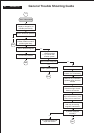

Remark: At first power on w/o signal LED will be orange blinking + message on screen.
7.2 Standard Test conditions
Unless otherwise specified, this specification is defined under the following conditions.
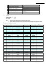
(1) Input signal : As defined in Timing table, 1680 x 1050
non-interlaced mode (1680X1050@60Hz 146.25MHz), signal
sources must have 75 ohm output impedance.
(2) Luminance setting : controls to be set to 300 nits with
full screen 100 % duty cycle white signal
(3) Warm up: more than 30 minutes after power on with signal supplied.
(4) Ambient light: 400 – 600 lux.
(5) Ambient temperature: 20 ± 5 °C
7.3 Test equipment
Personal computer with Windows 98/2000/XP
Luminance meter Minolta CA110
Videogenerator: Chroma 2000, 2135, 2250 or equivalent
Colour analyzer: Minolta or Chroma
10 times magnifier
Ruler / Template
Thickness gauge
Watt / Power Meter
7.4 Video Generator test sequence
Will be defined by TVI or its subcontracted quality providers.
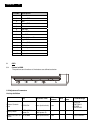
7.5 Analog input
Analog input R,G,B level: 0 - 850 mV max.
Polarity: positive, negative
Impedance: 75 Ω ± 1%
Sync: HV separate sync, composite sync,
7.6 Optical response time
Video Bandwidth: 165 MHz (dot rate)
Typical rise time 5 ms
7.7 Protection circuit
The monitor will not be damaged by:
missing vertical or horizontal sync pulse
improper vertical or horizontal sync pulse (picture must be black at improper signals,
unsynchronized pictures are not allowed
)
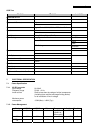
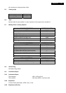
7.8 DDC
The monitor can support DDC 2 B and DDC-CI according to the latest VESA standard.
7.8.1 DDC Details
66 200VW8 LCD