


Product Information
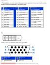
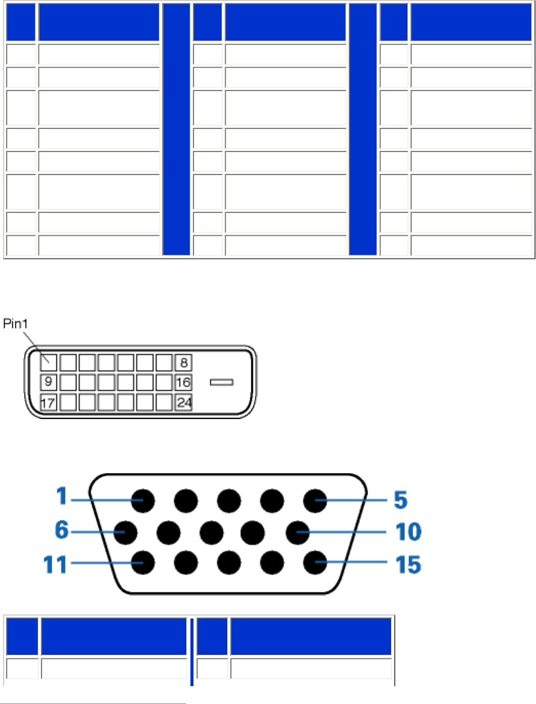
1. The digital only connector contains 24 signal contacts organized in three rows of eight contacts.
Signal pin assignments are listed in the following table:
Pin
No.
Signal
Assignment
Pin
No.
Signal
Assignment
Pin
No.
Signal
Assignment
1
T.M.D.S. Data2-
9
T.M.D.S. Data1- 17 T.M.D.S. Data0-
2
T.M.D.S. Data2+
10
T.M.D.S. Data1+ 18 T.M.D.S. Data0+
3
T.M.D.S. Data2/4
Shield
11
T.M.D.S. Data1/3
Shield
19
T.M.D.S. Data0/5
Shield
4
No connect
12
No connect 20 No connect
5
No connect
13
No connect 21 No connect
6
DDC Clock
14
+5V Power 22
T.M.D.S. Clock
Shield
7
DDC Data
15
Hot Plug Detect 23 T.M.D.S. Clock+
8
No connect 16 Ground (for +5V) 24 T.M.D.S. Clock-
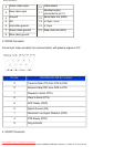
2. The 15-pin D-sub connector (male) of the signal cable:
Pin
No.
Assignment
Pin
No.
Assignment
1
Red video input
9
DDC +5V
file:///D|/My%20Documents/dfu/300WN5/english/300wn5/PRODUCT/PRODUCT.HTM (6 of 9)2005-02-16 10:33:08 AM
Downloaded From TV-Manual.com Manuals