


WWW.POLKAUDIO.COM/AMPS
9
ENGLISH
PA 12V AMPLIFIERS
8
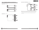
REAR PANEL CONNECTIONS
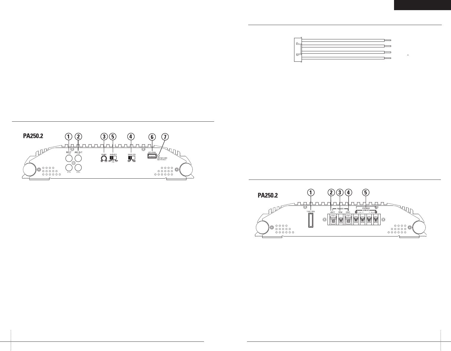
1.Fuse—These fusesprotect theamplifier against
internal electrical damageand aremeant to protect
the amplifieronly. All otherpower connections
should be fused atthe source.
2.(+) 12Volt Power—Connectthis terminalthrough
a FUSE or CIRCUIT BREAKERto thepositive terminal
of thevehicle batteryor thepositive terminalof an
isolated audio systembattery.
WARNING: Alwaysprotect this power wireby install-
ing afuse orcircuit breakerof theappropriate size
within 12 inchesof thebattery terminalconnection.
3.Remote TurnOn—This terminalturns onthe amplifier
when (+) 12volt isapplied toit. Connectit tothe remote
turn on leadof thehead unitor signal source.
4.Ground—Connect thisterminal directlyto thesheet
metal chassisof thevehicle, usingthe shortestwire
necessary tomake thisconnection. Always usewire
of thesame gaugeor largerthan the(+) 12volt power
wire. The chassisconnection pointshould be scraped
free ofpaint anddirt. Useonly qualitycrimped and/or
soldered connectorsat bothends ofthis wire. DONOT
connect thisterminal directlyto thevehicle battery
ground terminalor anyother factoryground points.
5.Speaker Terminals—Connectsubwoofers tothese
terminals. (Referto the SpeakerWiring Diagrams
section of thisguide.)
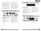
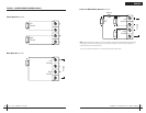
FIGURE 3—AMPLIFIER CONNECTIONS—REAR (PA250.2)
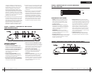
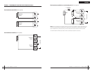
FIGURE 2—LED/FAN HARNESS
BLACK
BLUE
BLACK
RED
-
+
-
+
TOLEDs
TOF AN
FRONT PANEL CONNECTIONS/CONTROLS
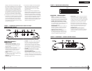
1.RCA InputJacks—Accepts linelevel outputsfrom
headunitsor signalprocessors atvoltages between
250mVand7.5 volts.
2.RCA LineOutput Jacks—Thesepass-through
RCAjackscan beused tosend theinput signal
toasecond amplifier.
3.Gain Control—Controlsthe amplifier’ssensitivity
andisused tomatch theinput levelof theamplifier
totheoutput levelof thesignal source.
4.Bass EQSwitch—Adds 8dBadditional bassboost
tothespeaker outputwhen on.
5.X-Over SelectionSwitch (HPF,Flat, LPF)—
TheHPFattenuates lowfrequencies andis used
withmid-rangespeakers andtweeters. Flatdoes not
attenuateanyfrequencies andis forfull rangespeaker
systems.LPFattenuates highfrequencies andis used
forsubwoofers.
6.Light Bar/FAN—Allowsconnection ofan optional
LEDlightbar oroptional coolingfan forthe amplifier.
7.Status LED—Willilluminate GREENto indicatethe
amplifierison andoperating normally,and willbe
illuminatedREDif theamplifier shutsdown dueto
shortcircuit,DC offset,or overheatingdetected by
onboardprotectioncircuitry.
FIGURE 1—AMPLIFIER CONNECTIONS/CONTROLS—FRONT (PA250.2)
wireused.IASCA andother autosound competition
organizationshavecharts availablefor this;you can
alsofinda chartin theMECP studyguide. Minimum
wiregaugerecommendations forthe individualampli-
fiersarelisted onthe specificationpage. Alwaysuse
thesame gaugewirefor theamplifier groundthat you
useforthe powerwire. Besure toexamine thebattery
groundcableof thevehicle, andif necessary,upgrade
itbyadding anadditional groundwire thatis thesame
gaugeasthe amplifier’spower wire.Remember, the
amplifiercanonly deliverits ratedoutput whenit isnot
currentlimitedby thepower andground supplywires.
9.This amplifieris designedto drivea speakerload
thatmeasuresfrom 2to 8ohms. Keepin mind
thatheatis thelong-term enemyof automotiveelec-
tronicsandthe loweryour speakerload, themore heat
isgenerated.For low-impedancespeaker applications
orrestrictedventilation installations,an externalcooling
fanmaybe advisable.
10.Batteryand groundconnections tothevehicleshould
bemadewith crimpedring terminalsof theappropriate
size(surfacearea iswhat counts;)soldering thetermi-
nalsaftercrimping isalso recommended.
11.Dueto thehigh-frequency MOSFETswitching power
supply,filteringthe powercable isnot generallyrequired
(rememberthatthe ampcan’t deliverfull outputif the
powersupplyis restricted.)Proper groundingof the
signalsourceis mandatoryfor theamplifier toreach
itsperformancepeak. Ifthe RCAinputs arenotgrounded
adequatelyviathe signalsource, electricalnoise from
thevehiclemay bepicked upin thesystem.