


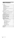
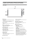

Location and Function of Parts and Controls
13
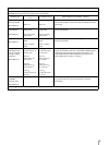
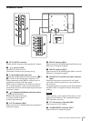
j Input select buttons
Press the button to monitor the signal input to each
connector.
A-1, A-2, B-1 and B-2 buttons are used when an
optional input adaptor has been installed in the option
slot.
COMPOSITE button: to monitor the signal through
the COMPOSITE IN connector
Y/C button: to monitor the signal through the Y/C IN
connector
RGB button: to monitor the RGB signal through the
connectors for the R/G/B signal input
COMPONENT button: to monitor the component
signal through the connectors for Y/P
B/PR signal input
A-1 button: to monitor the signal from connector 1
(the connectors for the R/G/B signal input in BKM-
229X) of the input adaptor installed to the option slot
A
A-2 button: to monitor the signal from connector 2
(the connectors for Y/P
B/PR signal input in BKM-
229X) of the input adaptor installed to the option slot
A
B-1 button: to monitor the signal from connector 1
(the connectors for the R/G/B signal input in BKM-
229X) of the input adaptor installed to the option slot
B
B-2 button: to monitor the signal from connector 2
(the connectors for Y/P
B/PR signal input in BKM-
229X) of the input adaptor installed to the option slot
B
HD15 button: to monitor the signal through the
HD15 input connector
DVI button: to monitor the signal through the DVI-D
input connector
k Function buttons
You can turn the assigned function on or off.
The factory setting is as follows;
F1 button: EXT SYNC
F2 button: SCAN
F3 button: ASPECT
F4 button: MULTI DISPLAY
You can assign the function from among SCAN,
ASPECT, EXT SYNC, BLUE ONLY, MONO, MULTI
DISPLAY, APA and MIRROR IMAGE in FUNCTION
BUTTON SETTING of the USER CONFIG menu (see
page 29).
For details of the function assigned to the function
button, see page 29.
l USER MEM (user memory) button
Press to load the picture settings saved in the USER
MEMORY menu (on page 31).