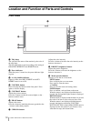
Location and Function of Parts and Controls
14
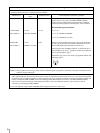
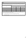
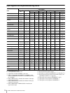
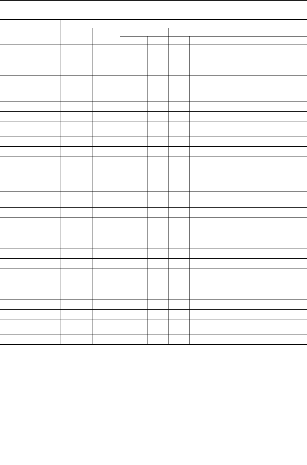
Input signals and adjustable/setting items
a : Adjustable/can be set
× : Not adjustable/cannot be set
*1 Adjustment of SUB CONTROL is the same.
*2 When a component signal (480/60I or 480/60P) is input
and the COMPONENT LEVEL is set to SMPTE, this can
be switchable.
*3 When a BKM-227W is installed, the number of the input
connector is increased.
*4 When a BKM-229X is installed, the number of the input
connector is increased.
*5 When a BKM-220D or BKM-243HS is installed, the
signal can be input.
*6 When a BKM-243HS is installed, the signal can be input.
*7 Only the interlace signal is input.
*8 The signal can operate with PRESET 2 to 6. (See page 37.)
*9 The signal can only be selected in the main display. (See
“SUB INPUT SELECT” on page 28.)
*10 The signal cannot operate with PRESET 7 and 8.
*11 The signal can only operate with PRESET 1.
*12 The signal can only operate with PRESET 6.
Input signal
Item Video*
3
,
Y/C*
3
B & W*
3
Component*
4
RGB*
4
SDI Computer
SD HD SD HD D1*
5
HD*
6
DVI HD15
CONTRAST*
1
a a a aaaaa a a
BRIGHT*
1
a a a aaaaa a a
CHROMA*
1
a × a aaaaa a a
PHASE*
1
a
(NTSC)
× a aaaaa a a
APERTURE
a a a aaaaa a a
COLOR TEMP
a a a aaaaa a a
COLOR SPACE
a a a aaaaa a a
AUTO CHROMA/
PHASE
a
×
aa
××
×× × ×
ACC
a
× × ××××× × ×
CTI
a × a ××××× × ×
V SHARPNESS
aaa× a × a ×× ×
MATRIX*
2
××a
×
×××× × ×
COMPONENT LEVEL
××
a
(480/60I)
×××
×
×× ×
NTSC SETUP
a
(NTSC)
a
(480/60I)
× ××××× × ×
SCAN
a a a aaaaa ×*
8
×*
8
GAMMA
a a a aaaaa a a
ASPECT*
10
aaa× a × a ××*
12
×*
12
BLUE ONLY
a × a aaaaa ××
MONO
a × aa××aa ××
APA
× × × ××××× × a*
11
SIZE
× × × ××××× × a
SHIFT
a a a aaaaa × a
PITCH
× × × ××××× × a
DOT PHASE
× × × ××××× × a
POWER SAVING
a a a aaaaa a a
PICTURE DELAY
MIN*
7
a a a aaaaa ×*
8
×*
8
MULTI DISPLAY
a a a aaaaa a*
9
a*
9


