


Location and Function of Parts and Controls
15
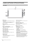
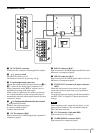
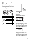
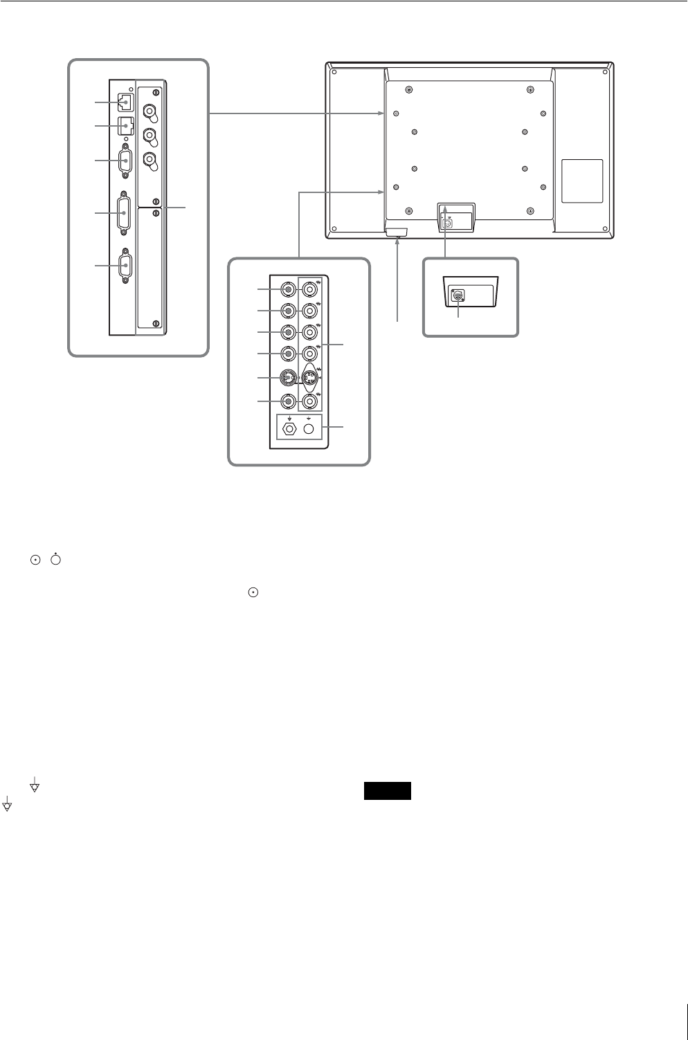
Side/Rear Panel
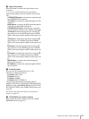
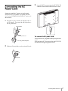
a DC 5V/24V IN connector
Connect the DC connector of the supplied AC adaptor.
b / (power) switch
The power is turned on or off.
The monitor is turned on by pressing side .
c Loop-through output connectors
Outputs the signals input to the input connectors (5 to
0). Connect to the analog input (composite, Y/C,
analog component, analog RGB or external sync) of
equipment, according to the input signal.
When a cable is connected to one of these connectors,
the 75-ohm termination of the corresponding input is
automatically released, and the signal input to the input
connector is output.
d /I (Equipotential/Function Earth) terminal
(equipotential) terminal
Connects the equipotential plug.
I (function earth) terminal
Connects the earth cable.
e G/Y IN connector (BNC)
Input connector for G of RGB signals and component Y
(luminance) signals.
f B/P
B IN connector (BNC)
Input connector for B of RGB signals and P
B (blue color
difference) of component signals.
g R/P
R IN connector (BNC)
Input connector for R of RGB signals and P
R (red color
difference) of component signals.
h EXT SYNC IN (external sync input) connector
(BNC)
When this unit operates on an external sync signal,
connect the reference signal from a sync generator to
this connector.
To use the external sync signal, press the function button
that EXT SYNC is assigned (F1 button at the factory
setting).
Note
When inputting a video signal with the jitters, etc. the
picture may be disturbed. We recommend using the
TBC (time base corrector).
i Y/C IN connector (4-pin mini-DIN)
Input connector for Y/C signals.
j COMPOSITE IN connector (BNC)
Input connector for composite signals.
5V24V IN
+5V
+24V
DC
IN G/Y OUT
IN B/P
B OUT
IN R/P
R OUT
IN
EXT
SYNC
OUT
IN
Y/C
OUT
IN
COMPOSITE
OUT
1
2
5
qs
qd
qf
qg
qh
3
qa
4
0
9
8
7
6