


40-EN
Installation and Connections
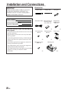
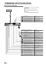
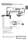
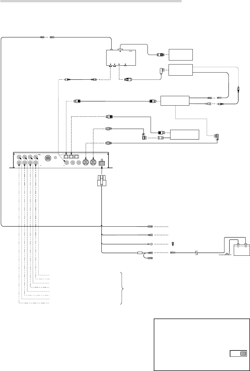
• PXA-H700 + DVA-7996 Head Unit + CD Changer + Navigation
System + Monitor + External Amplifier
NOTE
Depending on the type of monitor used in the system, a separate
RGB conversion cable (KWE-503N) may be required. In addition,
connections are different from the ones shown above when
connecting to an all-purpose monitor. Also refer to the operating
instructions of the KCE-900E. For details, contact your store of
purchase or an Alpine Information Center.
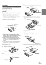
Please observe the following when using Fiber Optic
Cable.
• Do not coil the Fiber Optic Cable smaller than a 30mm radius.
• Do not place anything on top of the Fiber Optic Cable.
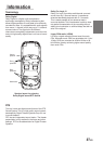
Battery
NAVIGATION
INPUT
REMOTE INPUT
VIDEO OUTPUT
RGB
RGB OUTPUT
GUIDE OUTPUT
NTSC VIDEO
OUTPUT
NTSC
Blue/White
Blue/White
Not used in this system
To External Amplifier Remote ON Cable
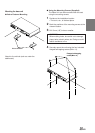
Connect to a metal part of
chassis body with a screw.
Remote OUT Cable
Remote ON Cable
Grounding Cable
Battery Power Cable
Rear Output (L)
Rear Output (R)
RCA
connection
cable
To
Video
Input
Jack
RGB Cable
(Sold Separately)
Remote Control
Output Cable
Remote Control
Input Cable
Video Output
Cable
Guide Control Cable
Yellow
Navigation
KCE-900E
(Sold Separately)
DVA-7996
Head Unit
Fiber Optic Cable (
Sold Separately
)
Monitor
(TME-M790 etc.)
White/Green
White/Brown White/Brown
Front 1 Output (L)
Front 1 Output (R)
Front 2 Output (L)
Front 2 Output (R)
RCA connection cable
Guide Control Cable
White/Green
Ai-NET Compatible
CD Changer
★★
Ai-NET Cable
(Included with CD Changer)
Fiber Optic Cable
(Sold Separately)
Ai-NET Cable (Included)
★
Center Output or Subwoofer Output (L)*
Subwoofer Output or Subwoofer Output (R)*
To External
Amplifier
(L)
(R)
FRONT 1
(FULL RANGE
/TWEETER)
FRONT 2 REAR
SUBWOOFER
CONTROL UNIT
MIC
GUIDEINPUTOUTPUT (L) (R)
Ai–NET IN
ANALOG 2
ANALOG 1
CHANGER IN
ANALOG 3
POWER SUPPLY
CHG
DIGITAL 2
CD
DIGITAL 1
DVD
DIGITAL 3
CENTER
SELECTABLE
SUBWOOFER
NOTES
★ When connecting a Optical Digital CD
Changer
★★ When connecting a Optical
Digital CD Changer, change
the Digital/Analog switch of
the CD Changer to “2”
(Digital Output)
12
* When the subwoofer is connected to the
center speaker output jack, it becomes
subwoofer output (L or R).
In this case, change the setting of the
center speaker to subwoofer in “Setting
the speakers” (page 4).