


3-83-8
3-83-8
3-8
Chapter 3: Motherboard infoChapter 3: Motherboard info
Chapter 3: Motherboard infoChapter 3: Motherboard info
Chapter 3: Motherboard info
6.6.
6.6.
6.
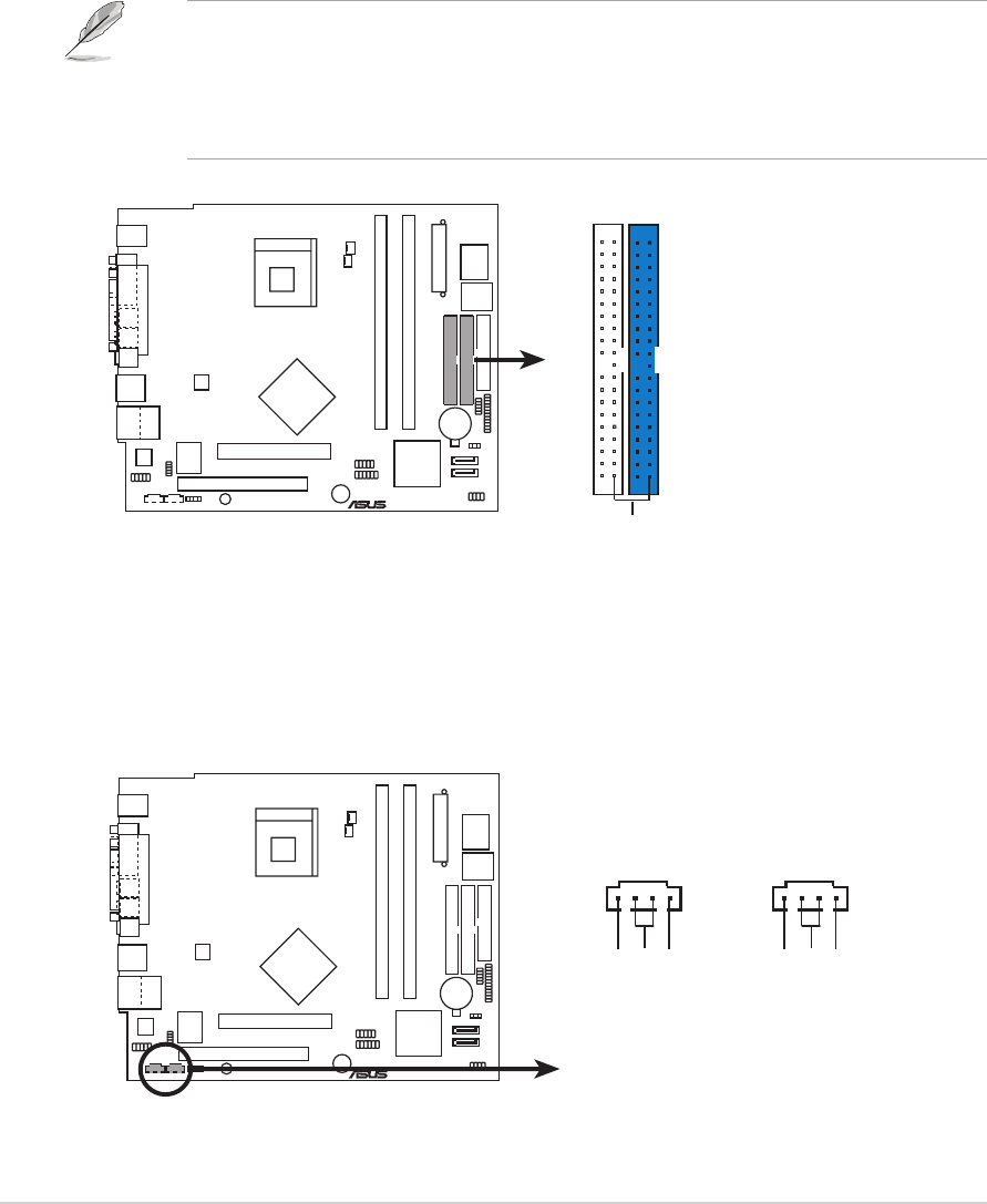
IDE connectors (40-1 pin PRI_IDE, SEC_IDE)IDE connectors (40-1 pin PRI_IDE, SEC_IDE)
IDE connectors (40-1 pin PRI_IDE, SEC_IDE)IDE connectors (40-1 pin PRI_IDE, SEC_IDE)
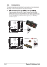
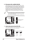
IDE connectors (40-1 pin PRI_IDE, SEC_IDE)
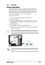
These connectors are for Ultra DMA 100/66 signal cables. The Ultra
DMA 100/66 signal cable has three connectors: a blue connector for
the primary IDE connector on the motherboard, a black connector for
an Ultra DMA 100/66 IDE slave device (optical drive/hard disk drive),
and a gray connector for an Ultra DMA 100/66 IDE master device
(hard disk drive). If you install two hard disk drives, you must
configure the second drive as a slave device by setting its jumper
accordingly. Refer to the hard disk documentation for the jumper
settings.
• Pin 20 on the IDE connector is removed to match the covered hole
on the Ultra DMA cable connector. This prevents incorrect insertion
when you connect the IDE cables.
• Use the 80-conductor IDE cable for Ultra DMA 100/66 IDE devices.
P4P8T
®
P4P8T IDE connectors
NOTE: Orient the red marking
s
(usually zigzag) on the IDE
ribbon cable to PIN 1.
SEC_IDE
PIN 1
PRI_IDE
7.7.
7.7.
7.
Internal audio connectors (4-pin AUX1, CD1)Internal audio connectors (4-pin AUX1, CD1)
Internal audio connectors (4-pin AUX1, CD1)Internal audio connectors (4-pin AUX1, CD1)
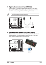
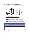
Internal audio connectors (4-pin AUX1, CD1)
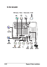
These connectors allow you to receive stereo audio input from sound
sources such as a CD-ROM, TV tuner, or MPEG card.
P4P8T
®
P4P8T Internal audio connectors
AUX1 (White) CD1 (Black
)
Right Audio Channel
Left Audio Channel
Ground
Right Audio Channel
Left Audio Channel
Ground