


2-Way RF Compact Color Touchpanel Crestron STX-1550C
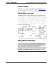
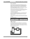
These three signal names should drive an INTERLOCK symbol so that the system
can “remember” which page was shown last on the touchpanel. The outputs of the
INTERLOCK are assigned unique names: TV-FLIP-F, VCR-FLIP-F, and
PROJ-FLIP-F.
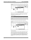
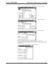
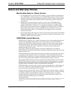
Finally, the corresponding feedback signals from the INTERLOCK must match the
appropriate page join number. For this example, the page join numbers shown in the
table below correlate to the INTERLOCK output signals.
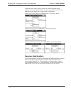
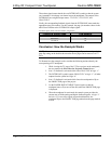
Feedback Signal Name with Join Number Assignments
FEEDBACK SIGNAL NAME JOIN NUMBER
PROJ-FLIP-F 23
VCR-FLIP-F 24
TV-FLIP-F 25
Conclusion: How the Example Works
NOTE: Since the control system is controlling the page flips on the touchpanel, the
page flip setting on the buttons shown on the device pages can be removed via VT
Pro-e.
To illustrate how the example works, consider the following actions taken by the
user operating a STX touchpanel.
1. While viewing the TV page of the VT Pro-e project on the touchpanel,
the user touches the Press Here for Projector Control button.
2. Join # 22 feedback is activated which forces PROJ-FLIP to logic “1”.
3. The INTERLOCK symbol outputs PROJ-FLIP-F as logic “1”; all other
outputs from the symbol are logic “0”.
4. Join # 23 feedback is activated which forces the touchpanel to flip to
the PROJECTOR page of the project.
5. Let the POWER DOWN TIMEOUT period expire so that the
touchpanel turns off (or turn off the unit) while the PROJECTOR page
is displayed.
6. When the touchpanel is reactivated, the control system provides the
current state of all the analog and digital feedback signals. A logic “1”
for Join # 23 is one of the signals resynced and therefore, the
touchpanel flips to the PROJECTOR page rather than the page marked
as first.
26 • 2-Way RF Compact Color Touchpanel: STX-1550C Operations Guide - DOC. 5812A