


R4140G FLAME SAFEGUARD PROGRAMMING CONTROLS
60-2337—3
20
Ignition Trials
70 seconds—M4A closes; power is applied to terminals
18, 5 and 6, energizing the ignition transformer and
pilot valve (and terminal 7, main oil valve solenoid, if
using direct spark ignition of oil).
— When flame is detected, relay 2K pulls in, 2K2
opens, and the LS HTR stops heating; 2K1 and
2K3 close.
75 seconds—M9B opens; 5 second ignition (terminals 18)
de-energizes (pilot only until 80 seconds).
76 seconds—M3A closes, bypassing the low fire switch
and the timer switch.
80 seconds—M2B opens; pilot or ignition trial ends; flame
must be detected by this time (2K pulled in and 2K1
closed) or safety shutdown occurs and the lockout
switch trips.
— M2A closes; power is applied to terminal 7,
energizing the main fuel valve(s).
— M11B opens; prevents 2K from pulling in after this
time.
90 seconds—M6B opens; 10 second interrupted pilot/
ignition (terminal 5) de-energizes.
110 seconds—M4A opens; 30 second interrupted pilot/
ignition (terminal 6) de-energizes if jumper was
not
installed on back of programmer.
140 seconds—M12B opens; 60 second interrupted pilot/
ignition (terminal 6) de-energizes if jumper was
installed
on back of programmer.
148 seconds—M8A closes, M8B opens; firing rate motor is
released to modulate under control of the Series 90
Controller.
155 seconds—M5B opens; timer stops with the system in
the Run condition.
Run Period (Burner is Firing)
Postpurge and Stop
155 seconds—When the operating setpoint is reached, the
burner controller contacts open; relay 1K and the main
fuel valve(s) (terminal 7) de-energizes.
— 1K2 closes; timer motor starts; postpurge begins.
— When flame goes out, relay 2K drops out.
168 seconds—M8A opens; firing rate motor stops
modulating under control of the Series 90 Controller.
174 seconds—M8B closes; firing rate motor drives toward
low fire position (closed).
180 seconds—M1B opens; timer and burner motor stop;
cycle ends.
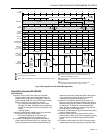
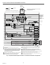
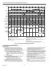
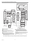
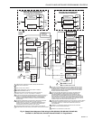
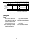
Fig. 13 shows all contacts in the standby position (zero
seconds). The opening and closing times are shown adjacent
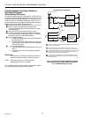
to each timer contact. Refer to Fig. 14 and the Step-by-Step
Operation section.