


R4140G FLAME SAFEGUARD PROGRAMMING CONTROLS
60-2337—3
26
Optional Hookups for Two-Stage Switching or
Intermittent Pilot/Ignition
(Nonmodulating Oil Burners)
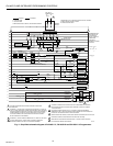
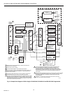
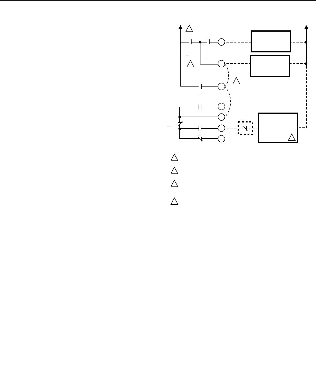
If modulation of the firing rate is not required, an R4140G can
be used to provide two-stage switching for an oil burner; also,
an R4140G with interrupted pilot/ignition on terminal 6 can be
wired to provide an intermittent pilot/ignition. Refer to Fig. 17
for the necessary wiring changes and make these changes in
the field wiring to the Q520A Wiring Subbase.
³ Remove all wiring from terminals 5,6,7,10,11, 12, and 14.
· Install a jumper wire between terminals 6 and 7.
(If using an R4140G1056 or R4140G1064, this jumper
is not necessary.)
» Install a jumper wire between terminals 7 and 11.
¿ Connect the ignition transformer between terminals 5
and L2 (for 20 second interrupted ignition), or between
terminals 6 and L2 (for intermittent ignition).
´ For two-stage switching:
a. Connect the first stage oil valve solenoid between
terminals 6 and L2.
b. Connect the second stage controller (if used) and
second stage oil valve solenoid in series between
terminals 12 and L2.
² For an intermittent pilot:
a. Connect the intermittent pilot between terminals 6
and L2.
b. Connect the main fuel valve between terminals
12 and L2.
IMPORTANT
The fuel valve or solenoid connected to terminal 12
must not exceed the electrical rating of terminal 7.
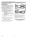
NOTE: The maximum Pilot or First Stage Flame-
Establishing Period is ten seconds.
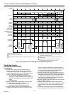
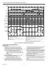
For a description of the Ignition Trials for this hookup, refer to
Fig. 18 and the Step-by-Step Operation section.
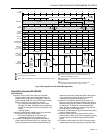
TO M2B, 2K1, AND L1
M4A
C-60
O-100
M6B
C-50
O-80
M8A C-100 O-112
M10B
O-4
C-45
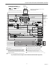
20 SECOND
INTERRUPTED
PILOT/IGNITION
INTERMITTENT
PILOT/IGNITION
OR 1ST STAGE OIL
VALVE SOLENOID
JUMPER
JUMPER
2ND STAGE
CONTROLLER
(IF USED)
MAIN FUEL VALVE
OR 2ND STAGE OIL
VALVE SOLENOID
(ENERGIZED AT
100 SECONDS)
REFER TO SCHEMATIC DIAGRAMS FOR COMPLETE INTERNAL WIRING
AND CONTACT SWITCHING.
M4A O-85 ON THE R4140G1106, AND R4140G1148; O-110 ON THE
R4140G1056, R4140G1064, R4140G1114, R4140G1122, AND R4140G1171.
JUMPER IS NOT NECESSARY TO OBTAIN INTERMITTENT PILOT/IGNITION
ON THE R4140G1056, OR R4140G1064; THESE MODELS PROVIDE
INTERMITTENT PILOT/IGNITION ON TERMINAL 6.
IF A 2ND STAGE CONTROLLER IS USED, THE 2ND STAGE OIL VALVE
SOLENOID IS NOT ENERGIZED UNTIL THE 2ND STAGE CONTROLLER
CONTACTS CLOSE.
M10060
M2A C-70 O-109.5
1
3
4
2
1
2
3
4
L2
5
6
7
10
11
12
14
R4140G PARTIAL SCHEMATIC
Fig. 17. Field wiring changes (dashed) to provide
two-stage switching or intermittent pilot/ignition
for a nonmodulating oil burner.