


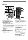
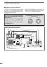
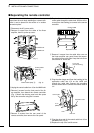
■ System interconnections
1 or 2 Icom 100 W HF transceivers can be connected
as exciters to the IC-PW1/EURO. Non-Icom trans-
ceivers can be used, however, band selection will not
be synchronized for each exciter.
See the following diagrams for making connections
between the IC-PW1/EURO and an exciter (transceiv-
er). See p. 5 for AC power cable connection.
7
2
INSTALLATION AND CONNECTIONS
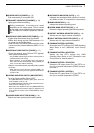
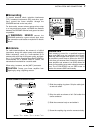
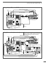
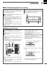
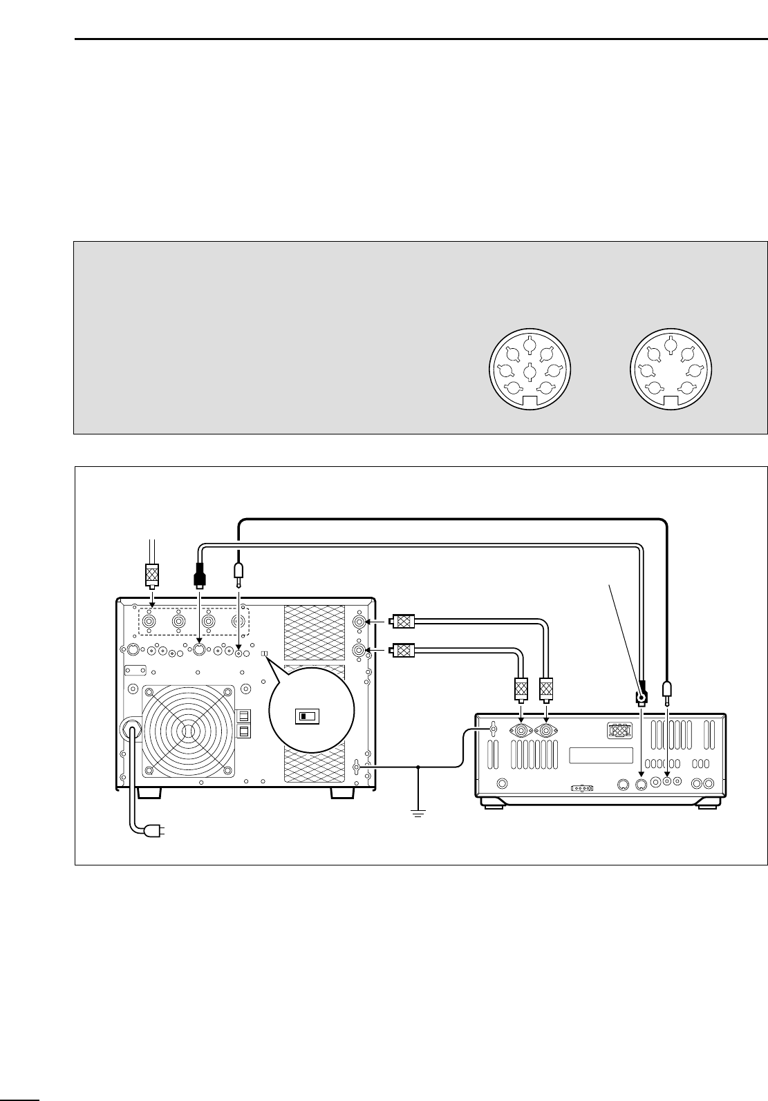
• Using 1 Icom exciter (transceiver)
ANT
ACC-1
ANT2 ANT1 ACC(2) REMOTE
REMOTE
INPUT1
INPUT2
Connect
[INPUT2]
if necessary.
GND
GND
IC-PW1/EURO
IC-756
Ground
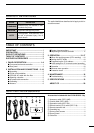
Coaxial cable (supplied)
Coaxial cable
(optional)
ACC cable (supplied)
Be sure to connect the cable
to the 7-pin ACC(2) jack.
Remote control cable (supplied)
To an
antenna
EXCITER
1 1&2
AC outlet
(IC-PW1 : 100–120/220–240 V
IC-PW1EURO : 230 V)
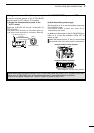
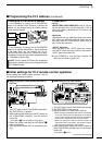
CAUTION!: When connecting the supplied ACC
cable to an Icom transceiver, be sure to connect the
cable to the 7-pin [ACC(2)] jack on the exciter
(transceiver) side.
If the ACC cable is connected to the 8-pin [ACC(1)]
jack, the protector circuit in the IC-PW1/EURO will
not able to read the ALC signal. If operation contin-
ues using this setup, damage (including the possibil-
ity of explosion) to the connected transceiver and/or
IC-PW1/EURO will occur.
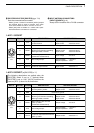
1
2
3
4
5
6
7
1
2
3
4
5
6
7
8
Icom standard 8 and 7-pin accessory jacks
(transceiver side)
[ACC(1)] [ACC(2)]