


20
5
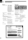
SPECIFICATIONS
INSTALLATION NOTES
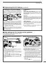
For amateur base station installations it is recom-
mended that the forwards clearance in front of the an-
tenna array is calculated relative to the EIRP (Effective
Isotropic Radiated Power). The clearance height below
the antenna array can be determined in most cases
from the RF power at the antenna input terminals.
As different exposure limits have been recommended
for different frequencies, a relative table shows a
guideline for installation considerations.
Below 30 MHz, the recommended limits are specified
in terms of V/m or A/m fields as they are likely to fall
within the near-field region. Similarly, the antennas
may be physically short in terms of electrical length
and that the installation will require some antenna
matching device which can create local, high intensity
magnetic fields. Analysis of such MF installations is
best considered in association with published guidance
notes such as the FCC OET Bulletin 65 Edition 97-01
and its annexes relative to amateur transmitter instal-
lations. The EC recommended limits are almost identi-
cal to the FCC specified ‘uncontrolled’ limits and tables
exist that show pre-calculated safe distances for differ-
ent antenna types for different frequency bands. Fur-
ther information can be found at http://www.arrl.org/.
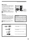
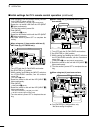
•Typical amateur radio installation
Exposure distance assumes that the predominant ra-
diation pattern is forwards and that radiation vertically
downwards is at unity gain (sidelobe suppression is
equal to main lobe gain). This is true of almost every
gain antenna today. Exposed persons are assumed to
be beneath the antenna array and have a typical
height of 1.8 m.
The figures assume the worst case emission of con-
stant carrier.
For the bands 10 MHz and higher the following power
density limits have been recommended:
10–144 MHz 2 W/sq m
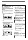
EIRP clearance heights by frequency band
1 Watts 2.1 m
10 Watts 2.8 m
25 Watts 3.4 m
100 Watts 5 m
1000 Watts 12 m
Forward clearance, EIRP by frequency band
100 Watts 2 m
1000 Watts 6.5 m
10,000 Watts 20 m
100,000 Watts 65 m
In all cases any possible risk depends on the transmit-
ter being activated for long periods. (actual recom-
mendation limits are specified as an average during 6
minutes) Normally the transmitter is not active for long
periods of time. Some radio licenses will require that a
timer circuit automatically cuts the transmitter after 1–2
minutes etc.
Similarly some types of emission, i.e., SSB, CW, AM
etc. have a lower ‘average’ output power and the as-
sessed risk is even lower.
Versions of the IC-PW1EURO which display
the “CE” symbol on the serial number seal,
comply with the essential requirements of
the European Radio and Telecommunication
Terminal Directive 1999/5/EC.
This warning symbol indicates that this
equipment operates in non-harmonised fre-
quency bands and/or may be subject to li-
censing conditions in the country of use. Be
sure to check that you have the correct ver-
sion of this radio or the correct programming
of this radio, to comply with national licens-
ing requirement.
NOTE: To meet European R&TTE regulations, the
OPC-853 AC cable with EMC filter must be connected
to the IC-PW1EURO.