


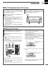
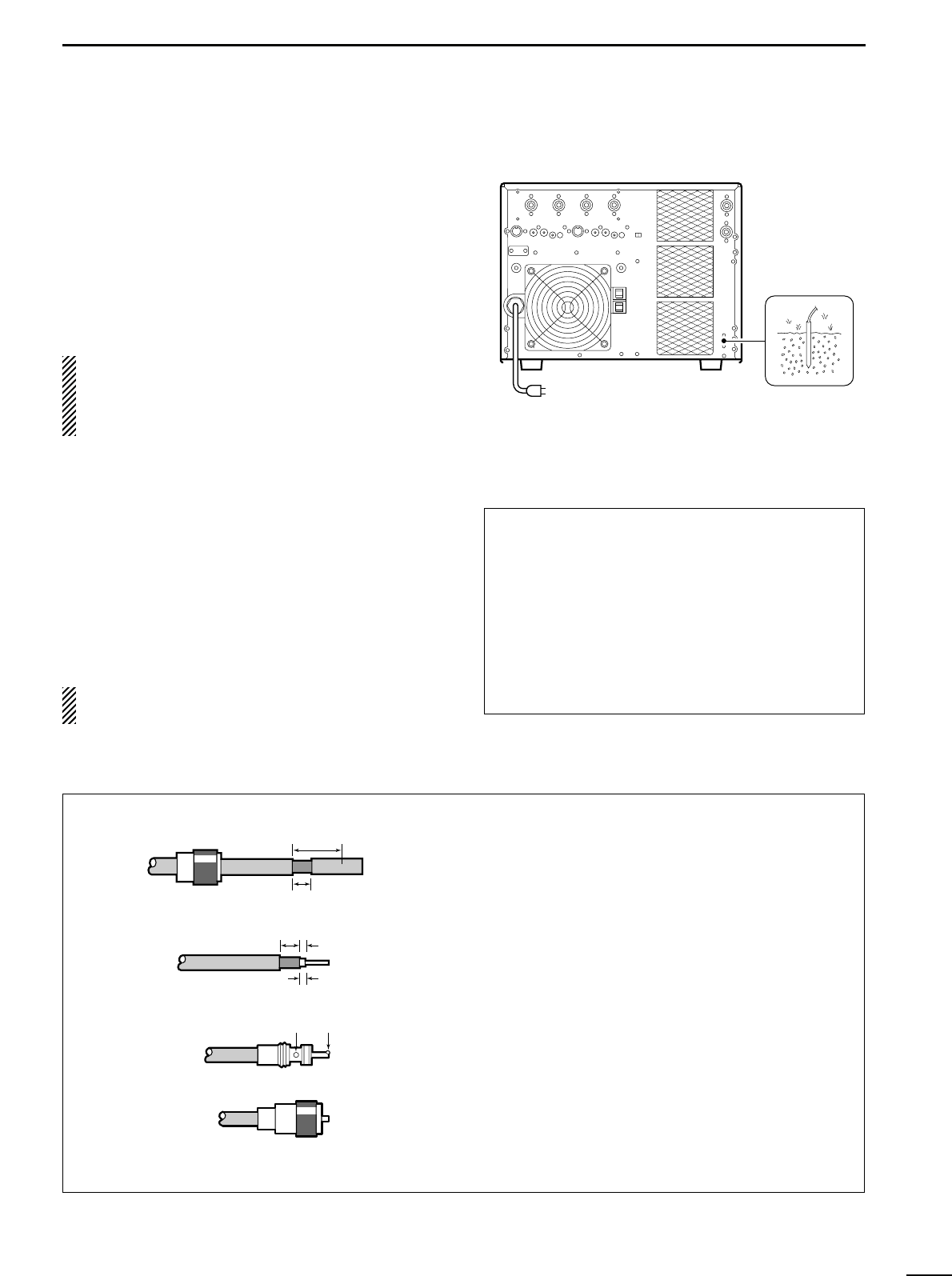
■ Grounding
To prevent electrical shock, television interference
(TVI), broadcast interference (BCI) and other prob-
lems, ground the linear amplifier through the
GROUND terminal on the rear panel.
For best results, connect a heavy gauge wire or strap
to a long earth-sunk copper rod. Make the distance
between the GROUND terminal and ground as short
as possible.
R WARNING: NEVER connect the
GROUND terminal to a gas or electric pipe, since
the connection could cause an explosion or electric
shock.
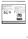
■ Antenna
For radio communications, the antenna is of critical
importance, along with output power and sensitivity.
Select antenna(s), such as a well-matched 50 Ω
antenna with more than 2 kW power rating, and feed-
line. 1.5:1 of Voltage Standing Wave Ratio (VSWR) is
recommended for a desired band. Of course, the
transmission line should be a coaxial cable.
When using 1 antenna, use the [ANT1] connector.
CAUTION: Protect your linear amplifier from
lightning by using a lightning arrestor.
6
2
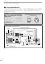
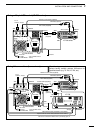
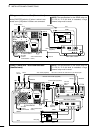
INSTALLATION AND CONNECTIONS
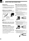
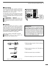
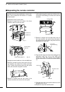
PL-259 CONNECTOR INSTALLATION
30 mm ≈
9
⁄8 in 10 mm ≈
3
⁄8 in 1–2 mm ≈
1
⁄16 in
q Slide the coupling ring down. Strip the cable jack-
et and soft solder.
w Strip the cable as shown at left. Soft solder the
center conductor.
e Slide the connector body on and solder it.
r Screw the coupling ring onto the connector body.
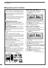
Antenna SWR
Each antenna is tuned for a specified frequency
range and SWR may be increased out-of-range.
When the SWR is higher than approx. 2.0:1, the lin-
ear amplifier’s power drops to protect the final FET.
In this case, an antenna tuner is useful to match the
linear amplifier and antenna. Low SWR allows full
power for transmitting even when using the antenna
tuner. The IC-PW1/EURO has an SWR meter to
monitor the antenna SWR continuously.
30 mm
10 mm (soft solder)
10 mm
1–2 mm
SolderSolder
Soft
solder
Coupling ring