


10
2
INSTALLATION AND CONNECTIONS
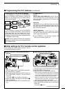
• Using non-Icom exciters (transceivers) when the IC-PW1/EURO’s power is OFF
To use the antenna selector of the IC-PW1/EURO
while the power is OFF, follow 1 of 2 methods.
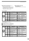
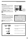
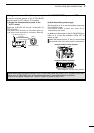
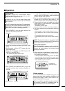
(1) Supply the antenna selector power to the
ACC-1 socket
Supply the 13.8 V DC, 0.5 A to pin 7 of the [ACC-1]/
[ACC-2] socket.
- Use [ACC-1] when the exciter is connected to [INPUT1].
- Use [ACC-2] when the exciter is connected to [INPUT2].
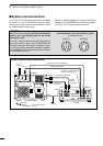
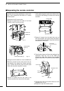
(2) Use the auxiliary power supply
Set the jumper to ‘2’ to use the auxiliary power sup-
ply as shown at right.
-The antenna selector functions even when the IC-
PW1/EURO power is OFF
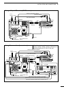
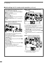
In addition set the jumper on the IC-PW1/EURO con-
troller to ‘2’ to turn the controller’s LEDs OFF as
shown at right.
When the jumper is set to ‘2,’ the CI-V control does
not function even if an Icom exciter is connected.
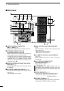
These diagrams show the factory defaults.
J3
J4
S3
12
1
2
•Jumper location of linear amplifier
•Jumper location of controller
1
2
3
4
5
6
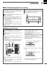
SEND ALC
RF
DC
GND
[ACC-1]
13.8 V DC
to IC-PW1/EURO [INPUT1]
to IC-PW1/EURO [GND]
IC-PW1/EURO (DIN)
Non-Icom exciter
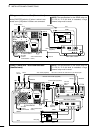
NOTE: When using the antenna selector of the IC-PW1/EURO while the power is OFF, as above, tuner intial-
ization of the IC-PW1/EURO may not be performed correctly if the applied voltage is insufficient.
Check that the applied voltage to pin 7 of [ACC-1]/[ACC-2] socket is 13.8 V DC.