


9
2
INSTALLATION AND CONNECTIONS
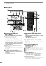
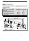
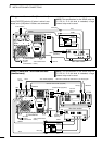
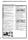
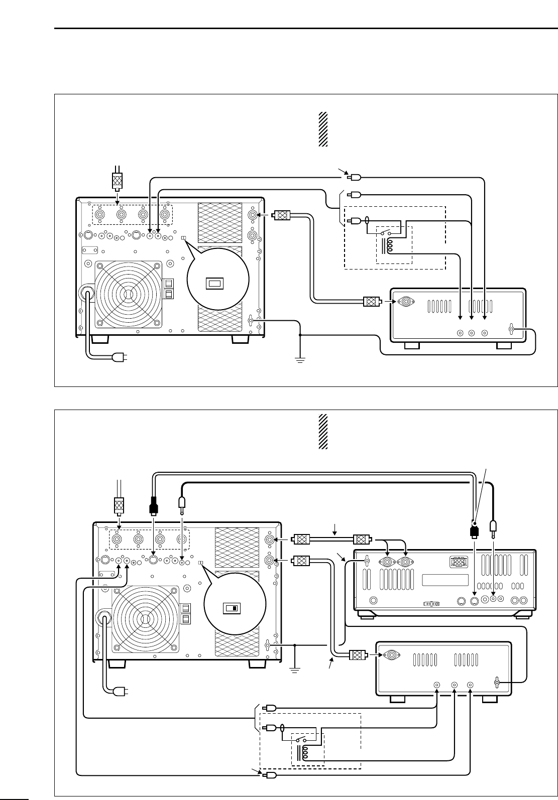
• Using 1 Icom and 1 non-Icom exciters
(transceivers)
NOTE: The specifications for the SEND relay are
5 V DC 0.1 A. If this level is exceeded, a large
external relay must be used.
ANT
ACC-1
ANT
ACC(2) REMOTE
REMOTE
INPUT1
INPUT2
Connect
ANT1 or
ANT2
GND
GND
IC-PW1/EURO
IC-756
Ground
Coaxial cable (supplied)
Coaxial cable
(optional)
ACC cable (supplied)
Remote control cable (supplied)
To an
antenna
EXCITER
1 1&2
RCA plug
ALC
ALC2
SEND2
SEND
SEND
Relay
DC power
Non-Icom exciter
GND
RF OUT
ALC
DC OUT
SEND
Be sure to connect the cable to the 7-pin ACC(2) jack.
AC outlet
(IC-PW1 : 100–120/220–240 V
IC-PW1EURO : 230 V)
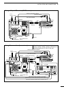
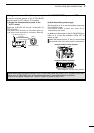
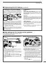
• Using a non-Icom exciter (transceiver)
Set the [EXCITER] switch to [1] when 1 exciter is con-
nected; set to [1&2] when 2 exciters are connected.
NOTE: The specifications for the SEND relay are
5 V DC 0.1 A. If this level is exceeded, a large
external relay must be used.
IC-PW1/EURO
Ground
Coaxial cable
(supplied)
To an antenna
ANT
Non-Icom exciter
INPUT1
RCA plug
ALC
ALC1
SEND1
SEND
SEND
Relay
DC power
GND
GND
ALCDC OUT SEND
RF OUT
EXCITER
1 1&2
AC outlet
(IC-PW1 : 100–120/220–240 V
IC-PW1EURO : 230 V)