


2
1
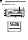
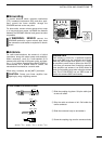
PANEL DESCRIPTION
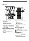
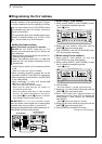
q POWER SWITCH [POWER] (p. 12)
Push momentarily to turn power ON.
w TRANSMIT INDICATOR [TRANSMIT] (p. 16)
Lights green while transmitting.
During transmission, a humming may sound
depending on the output power. This is caused
by the large current produced by the power sup-
ply and does not indicate equipment malfunc-
tion.
e ANTENNA TUNER INDICATOR [TUNER] (p. 16)
•Lights while the antenna tuner is activated.
•Blinks while tuning and the SWR becomes 1.5:1
or greater on the 50 MHz band.
•Goes out after slow blinking when antenna turner
cannot tune the selected antenna (SWR 1.5:1 or
greater).
r ANTENNA TUNER SWITCH [TUNER] (p. 17)
•Turns the antenna tuner ON and OFF (bypass)
when pushed momentarily.
- The [TUNER] indicator lights while the antenna tuner is
activated; blinks while tuning.
- While operating in the 50 MHz band, the antenna
tuner does not start automatically. Push [TUNER] for
2 sec. to tune the antenna manually.
•Starts to tune the antenna manually when pushed
for 2 sec.
- When the tuner cannot tune the antenna (SWR 1.5:1
or greater), the tuning circuit is bypassed automatical-
ly after 20 sec.
t LINEAR AMPLIFIER SWITCH [AMP/PROTECT]
Turns the linear amplifier ON and OFF.
- The [AMP/PROTECT] indicator lights green when the
linear amplifier is ON. (p. 16)
- The [AMP/PROTECT] indicator lights red when the pro-
tector circuit is activated. (p. 17)
- When the linear amplifier is OFF, the [AMP/PROTECT]
does not light and the exciter’s signal is applied to one
of the output connectors or the IC-PW1/EURO’s anten-
na tuner.
y LOWER BAND SELECTOR [DOWN] (p. 16)
Selects the lower operating band when pushed.
u AUTOMATIC INDICATOR [AUTO] (p. 16)
Indicates that automatic band selection is activat-
ed. (When an Icom CI-V transceiver is connected.)
i BAND INDICATORS (p. 16)
Indicate the selected operating band.
o UPPER BAND SELECTOR [UP] (p. 16)
Selects the higher operating band when pushed.
!0 OUTPUT ANTENNA SELECTOR [ANT] (p. 16)
Selects one of 4 output antenna connectors.
!1 INPUT ANTENNA SELECTOR [INPUT] (p. 16)
Selects one of 2 input antenna connectors.
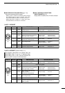
!2 TRANSMIT METER-2 [METER-2]
Shows the final FET’s voltage (V
D
), SWR (Standing
Wave Ratio) or ALC (Automatic Level Control)
level.
!3 TRANSMIT METER-2 SELECTOR
Selects the final FET’s voltage (V
D
), SWR
(Standing Wave Ratio) or ALC (Automatic Level
Control) level for transmit meter-2.
!4 TRANSMIT METER-1 SELECTOR
Selects the RF output power (P
O
), final FET’s cur-
rent (I
D
) or heatsink temperature (TEMP) for trans-
mit meter-1.
!5 TRANSMIT METER-1 [METER-1]
Shows the RF output power (P
O
), final FET’s cur-
rent (I
D
) or heatsink temperature (TEMP).