


14
3
OPERATION
■ Programming the CI-V address (continued)
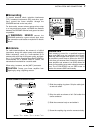
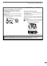
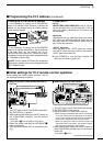
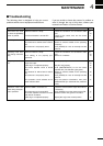
D Setting the IC-PW1/EURO’s address
It is not necessary to change the IC-PW1/EURO’s
default CI-V address of 54H. However, if desired, the
address can be changed using the internal address
switch illustrated below.
It is not necessary to change the IC-PW1/EURO’s
default CI-V address (default S3=5, S4=4). However,
in the case when you will connect two (2) IC-
PW1/EUROs like as above left1, please set a differ-
ent address number using the internal address switch
as illustrated as above right.
NOTE: Turn the power OFF when you are going to
change the address setting, then programming the
CI-V address again.
ï Other NOTE:
•IC-781;
NEVER TURN THE POWER OFF of the IC-781 dur-
ing the operation when you are using the IC-781 as
one of the exciters, otherwise the CI-V control may
be interrupted.
•Baud rate;
Higher baud rate (e.g. 9600 bps) gives quick opera-
tion. When you select an extra Low baud rate (e.g.
300 bps), then the IC-PW1/EURO needs max. 15
sec. to start the operation.
•“AUTO” baud rate;
When you want to use “AUTO” baud rate, turn the
non-“AUTO” baud rate exciter ON first, then turn the
“AUTO” baud rate exciter ON.
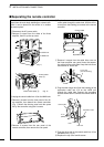
➥ Push [POWER] to turn the linear amplifier ON
then turn the exciter’s power ON.
REMOTE
Icom
exciter
IC-PW1
IC-PW1
Icom
exciter
Address switch
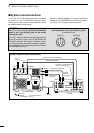
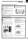
‘ Initial settings for CI-V remote control operation
Before setting the remote control operation, refer to
the following operating procedure.
ïï
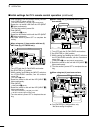
When using one (1) Icom exciter with one (1)
ANT line;
q Turn OFF both of the IC-PW1/EURO and exciter.
w Set [EXCITER] to [1] position.
e While pushing and holding the [INPUT] switch on
the IC-PW1/EURO controller, turn the exciter’s
power ON.
• LED [INPUT z] over the [INPUT] switch blinks.
r Rotate the exciter’s dial until the LED [INPUT z]
lights continuously.
t Turn the exciter’s power OFF to complete the set-
ting.
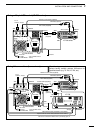
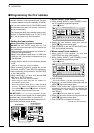
ïï
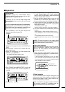
When using two (2) Icom exciters;
q Turn OFF both of the IC-PW1/EURO and exciters.
w Set [EXCITER] to [1&2] position.
e Set the exciter’s CI-V baud rate if required.
•
When selecting the different baud rate for each exciter,
“CI-V data” setting may fail depending on the exciter.
In such case, use the same baud rate for each exciter.
Each exciter’s frequencies may be synchronised.
• When connecting the “AUTO” baud rate exciter and
“Non-AUTO” baud rate exciter, the exciters’ frequen-
cies may not synchronize in some cases.
r While pushing and holding the [INPUT] switch on
the IC-PW1/EURO controller, turn the 1st exciter’s
power ON.
• LED [INPUT z] blinks.
☞
Continue to the next page
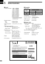
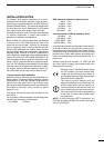
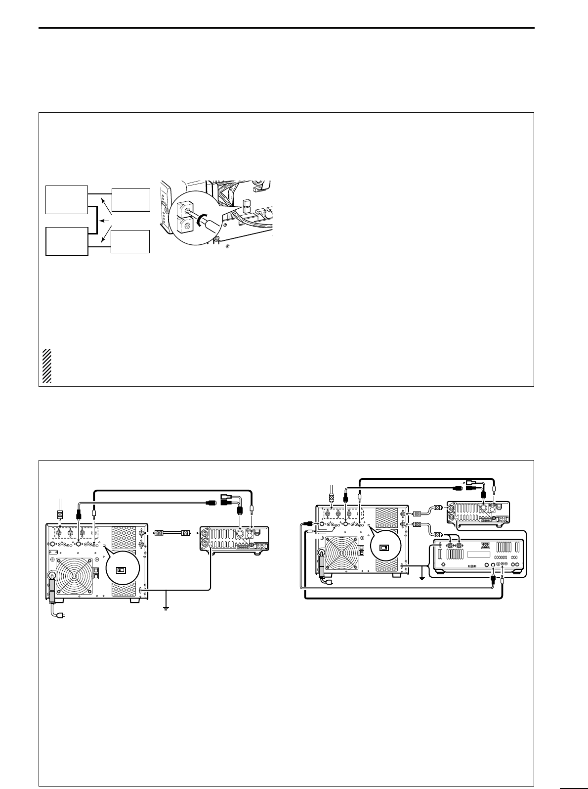
EXCITER
1 1&2
ANT
ACC-1
ANT1
ACC(2)
REMOTE
REMOTE
REMOTE
INPUT1
INPUT2
GND
GND
IC-PW1/EURO
ANT1 or 2
ACC (13 pins)
REMOTE
Optional ACC cable (included in OPK-5)
Optional remote control cable (included in OPK-5)
ACC (supplied)
GND
GND
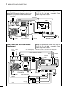
ACC-2
OPC-599 (optional)
IC-PW1/EURO
ACC cable (supplied)
ANT
ACC-1
ANT1
REMOTE
REMOTE
INPUT1
GND
GND
IC-706
ACC
OPC-599 (optional)
EXCITER
1 1&2