


13
3
OPERATION
The IC-PW1/EURO uses CI-V frequency data for
automatic selection of the operating band. Program
the exciter’s address to use this capability as follows:
For non-Icom exciters, the IC-PW1/EURO cannot
be controlled using the CI-V function, so this set-
ting is not necessary.
For transceivers which have multiple antenna con-
nectors for specified bands (e.g. IC-726, IC-729,
etc.), set the same as for 2 Icom exciters.
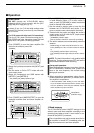
D Setting the Icom exciters
When connecting 2 or more CI-V devices:
DO NOT use the “AUTO” baud rate for CI-V
devices. We recommend that all CI-V devices are
set to 9600 bps.
•When using the same baud rate, the exciters’ fre-
quencies are synchronized.
•When using different baud rates (i.e. 4800 and
9600 bps, etc.), the exciters’ frequencies are not
synchronized.
q Confirm that the exciter’s CI-V transceive function
is ON.
- Refer to the instruction manual for details.
w
When connecting 2 exciters, connect the 1st and
2nd exciter to [INPUT1] and [INPUT2], respectively.
e When connecting 2 Icom exciters, set [EXCITER]
to the [1&2] position.
r When connecting 2 or more CI-V devices, DO
NOT set to “AUTO” baud rate.
- Refer to the instruction manual for details.
- When using the same baud rate, the exciters’ fre-
quencies are synchronized.
- When using different baud rates (i.e. 4800 and 9600
bps, etc.), the exciters’ frequencies are not synchro-
nized. [INPUTz] and [INPUTx] selection is automat-
ically selected using the exciter’s baud rate.
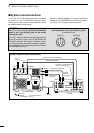
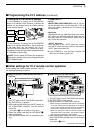
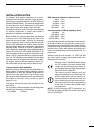
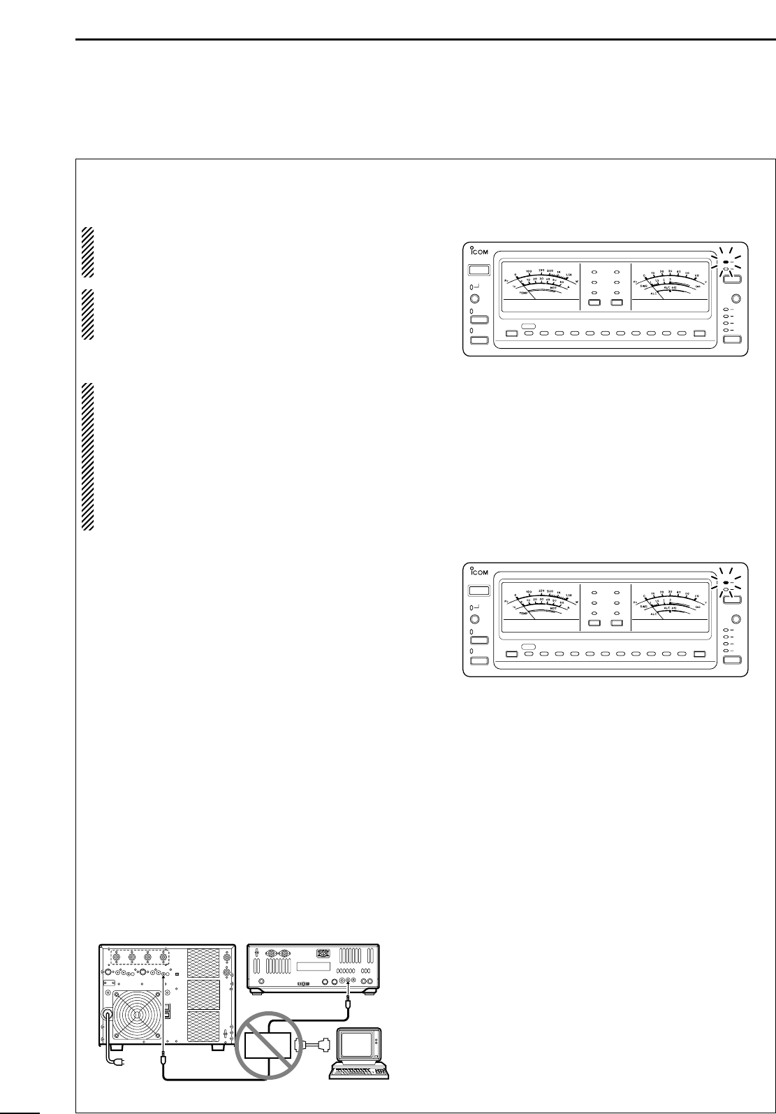
•DO NOT USE
CT
-17
CI
-
V LEVEL CONVERTER
to con-
nect the remote control signal line for band control
operation from an Icom exciter, or from the PC.
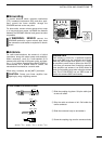
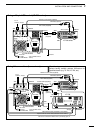
•Connect the supplied remote cable between the IC-
PW1/EURO and Icom exciter directly.
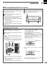
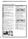
D When using 1 Icom exciter
q While pushing [INPUT], push [POWER] to enter
the CI-V address programming mode.
- [INPUTz] blinks.
w Rotate the Icom exciter’s tuning dial until the
[INPUTz] light continuously lights.
e Push [POWER] to turn the IC-PW1/EURO power
OFF and complete the setting.
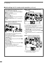
D When using 2 Icom exciter’s
q When using 2 Icom exciters, be sure that
[EXCITER] is set to the [1&2] position.
w While pushing [INPUT], push [POWER] to enter
the CI-V address programming mode.
- [INPUTz] blinks.
e Push [DOWN].
- The band indicators, [1.8]–[50], light continuously.
r Rotate the 1st Icom exciter’s tuning dial until the
[INPUTz] light continuously lights.
t When 1 Icom exciter and 1 non-Icom exciter are
connected, turn the power OFF to complete the
setting. When 2 Icom exciters are connected,
push [INPUT].
- [INPUTx] blinks when [INPUT] is pushed.
y Rotate the 2nd Icom exciter’s tuning dial until the
[INPUTx] light continuously lights.
u Push [POWER] to complete the setting.
☞
Continue to the next page…
HF/50MHz ALL BAND 1kW LINEAR AMPLIFIER
iPW1
POWER
TRANSMIT
TUNER
DOWN
UP
AUTO
AMP/
PROTECT
1.8 3.5 7 10 14 18 21 24 28 50
TEMP
ID
Po
ALC
SWR
VD
METER-1 METER-2
ANT
INPUT
z
x
z
x
c
v
HF/50MHz ALL BAND 1kW LINEAR AMPLIFIER
iPW1
POWER
TRANSMIT
TUNER
DOWN
UP
AUTO
AMP/
PROTECT
1.8 3.5 7 10 14 18 21 24 28 50
TEMP
ID
Po
ALC
SWR
VD
METER-1 METER-2
ANT
INPUT
z
x
z
x
c
v
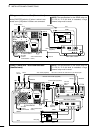
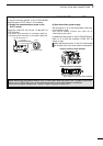
to REMOTE
Icom transceiver
(e.g. IC-756 etc.)
IC-PW1/EURO
to REMOTE
CT-17
PC
■ Programming the CI-V address