


17
3
OPERATION
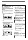
This linear amplifier has various protection circuits.
D ALC circuit
The ALC (Automatic Level Control) circuit automati-
cally limits RF output power by controlling the input
level of the exciter. This prevents transmission of dis-
torted signals when the input signal level exceeds the
allowable level.
The ALC activates under the following conditions:
- Output power of the linear amplifier exceeds 1 kW
- Antenna SWR becomes 2:1 or more
- Output power of the exciter exceeds 100 W
D Cooling fans
•The power supply cooling fans activate when the lin-
ear amplifier is activated and while transmitting.
•The antenna tuner cooling fans activate when the
antenna tuner is activated and while transmitting.
•All cooling fans activate when the heatsink temper-
ature of the final FETs reaches 50 °C (122 °F) or
more.
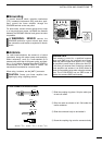
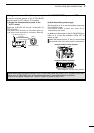
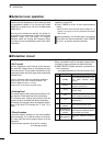
D Circuit breaker
If the circuit breaker activates or the linear amplifier
stops functioning, try to find the source of the prob-
lem, then push the circuit breaker button to fill the
white parts.
- Circuit breaker capacity: 20 A (U.S.A. version)
15 A (Europe version)
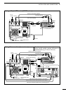
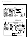
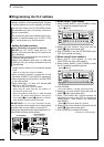
D Linear amplifier protection circuit
When a protection circuit is activated, a band indica-
tor blinks to show a problem as described below.
➥[AMP/PROTECT] lights red when a protection cir-
cuit is activated.
- Push [AMP/PROTECT] to cancel the protection circuit.
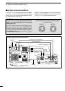
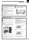
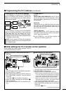
The built-in automatic antenna tuner can match the
antenna feed line impedance to 50 Ω when the feed
line impedance is within 16.7 to 150 Ω for HF bands
(VSWR 3:1) or within 20 to 125 Ω for 50 MHz bands
(VSWR 2.5:1).
Once the tuner matches an antenna, the tuning cir-
cuit condition is memorized as a preset point for each
frequency range (100 kHz steps, 70 ranges).
Therefore, when you change the frequency range,
the tuning circuit is automatically preset to the mem-
orized point.
This antenna tuner is also used when the linear
amplifier is turned OFF.
➥Push [TUNER] for 2 sec. to start manual antenna
tuning.
•When the tuner cannot tune the antenna (SWR 1.5:1 or
greater), the tuning circuit is bypassed automatically
after 20 sec.
While operating in the 50 MHz band, the antenna
tuner does not start automatically. Push [TUNER]
for 2 sec. to tune the antenna manually.
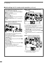
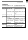
■ Protection circuit
■ Antenna tuner operation
Item Indication Possible cause
1
[TEMP]
The heatsink temperature of the
final FETs exceeds 100°C
(212°F).
2
[AUTO]
Power level of the 4 PA units
becomes unbalanced.
3
[ALC]
ALC control level exceeds the
control range.
4 [VD]
Output voltage of the internal
power supply exceeds 55 V DC.
5 [ID]
Current of the final FETs (I
D
)
exceeds 50 A.
6
Current band’s
indicator
Gain of the final FETs drops.
7
Selected and
current band’s
indicator
When transmitting with different
band selections between the lin-
ear amplifier and exciter.
8
[AMP/PROTECT]
The power supply has a malfunc-
tion.