


8
2
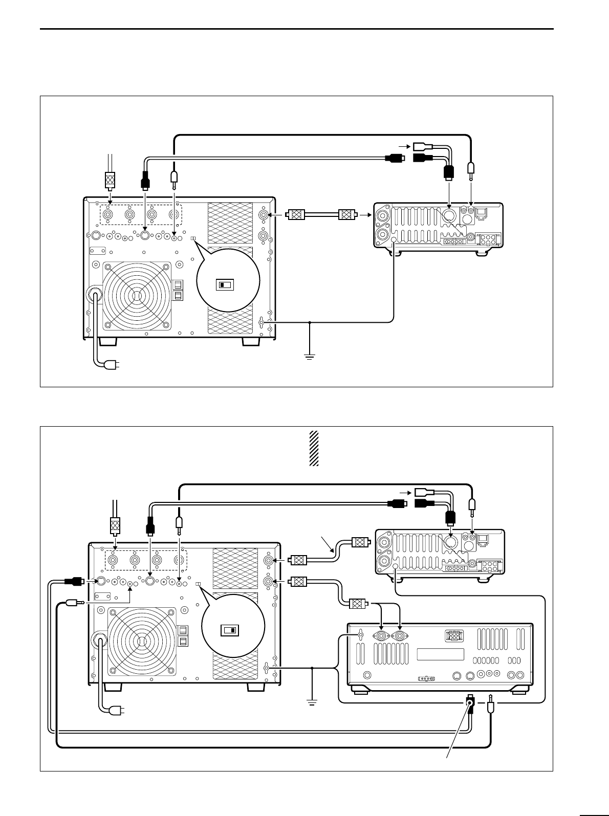
INSTALLATION AND CONNECTIONS
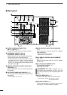
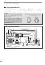
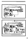
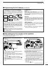
• Using a 13-pin ACC socket (IC-706 series)
IC-PW1/EURO
Ground
Coaxial cable
(supplied)
ACC cable (supplied)
Remote control cable (supplied)
To an
antenna
ANT
ACC-1
ANT1
REMOTE
REMOTE
INPUT1
GND
GND
IC-706 series
ACC (13 pins)
OPC-599 (optional)
EXCITER
1 1&2
AC outlet
(IC-PW1 : 100–120/220–240 V
IC-PW1EURO : 230 V)
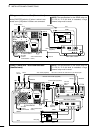
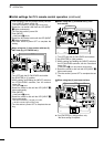
• Using 2 Icom exciters (transceivers)
The following connections also apply to trans-
ceivers having multiple antenna connectors for
specified bands (e.g. IC-726, IC-729, etc.)
IC-PW1/EURO
IC-756
Ground
Coaxial cable (supplied)
OPK-5
(optional)
ACC cable (supplied)
Remote control cable (supplied)
To an
antenna
OPC-599 (optional)
EXCITER
1 1&2
ANT
ACC-1
ACC-2
ANT1
ANT1 or 2
ACC REMOTE
REMOTE
REMOTEACC(2)
REMOTE
INPUT1
INPUT2
GND
GND
GND
IC-706 series
Optional ACC cable (includedn in the OPK-5)
Optional remote control cable (includedn in the OPK-5)
Be sure to connect the cable to the 7-pin ACC(2) jack.
AC outlet
(IC-PW1 : 100–120/220–240 V
IC-PW1EURO : 230 V)