


DESCRIPTION OF CONTROLS
DESCRIPTION OF CONTROLS
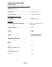
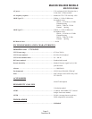
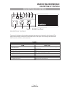
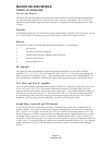
The controls, indicators and microphone/programming connector are located on the front panel. The
Monitor and Auxiliary buttons are located on the radio’s front panel. The following table details the
Mobile controls, indicators, and connections.
TABLE 2
Controls, Indicators, And Connections
ITEM FUNCTION
1. Channel Select Switch
Rotary switch, used to select one of 4 channels (max.) and to engage
scanning function
2. ON/OFF Volume Control
Main power switch and volume control. Fully counter clockwise is off
position
3. Microphone Connect Jack Used to connect the microphone to the mobile
4. Busy/Call/TX Tri-colored LED indicator
5. Auxiliary (AUX) Switch Used for control of after market accessories
6. Monitor Switch When pushed, monitors the chosen channel
7-10. Channel Indicator LED’s Indicates the channel when illuminated
MAXON SM-2000 MOBILE
DESCRIPTION OF CONTROLS
Page-9-
December 98
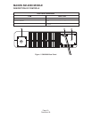
Figure 1 SM-2000 Front Panel