


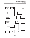

Receiver Audio Circuit
The receiver audio circuit is comprised of a low pass filter and an audio amplifier on the RF PCB.
Low Pass Filter
The low pass filter is configured from coil L227, capacitor C201 and resistor R206.AF signals from Pin 9
of IC109 are filtered by the low pass filter to remove any components of the 455kHz IF signal. The filtered
is passed to the high pass filter.
High Pass Filter
The de-emphasized audio signal from the high pass filter is fed to the audio amplifier (IC108).
Audio Amplifier
IC108 is the audio amplifier. The audio signal is passed to IC108. The gain of the amplifier is set by
resistor R153. The amplified audio signal at Pin 4 of IC108 is applied to the external speaker.
Mute (Squelch) Circuit
The squelch circuit switches off the audio power amplifier in the absence of audio signal. The squelch
circuit comprises a 50kHz pass band filter, squelch control (RV103) and a noise detect circuit.
The audio signal from Pin 9 of IC 109 is filtered by the 50kHz bandpass filter formed by L228, L229,
C191, C192, and C193. The noise in the IF pass band is accepted, frequencies in the voice frequency band
are rejected and noise present at the output of the filter is applied to the noise detect circuit via RV103.
RV103 is used to adjust the squelch sensitivity.
Noise Detect Circuit (SQ Board)
The noise detect circuit in conjunction with IC109 consists of transistor Q133 and Q132, thermistor TH101
and diode D125. Any noise signal present is applied to the base of Q133 of the SQ circuit from Pin 11 of
IC109. The signal is amplified by Q133 rectified by D11 and then buffered by Q132. The buffered signal
output is applied to the squelch trigger of IC109 Pin 12 via resistor R200. The squelch trigger out put (Pin
13 of IC109) is applied to the Micro controller on the Digital circuit. When noise is present, the voltage at
Pin 12 of IC109 exceeds 0.7V, the squelch trigger output is 0V (logic0) muting the receiver audio circuit.
When no noise is present the voltage at Pin 12 of IC109 is less than 0.7 and Pin 13 of IC109 is at 5V
(logic1), unmuting the audio circuit.
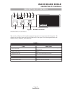
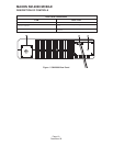
MAXON SM-2000 MOBILE
THEORY OF OPERATION
Page-17-
December 98