


Squelch Adjustment
1. Select a receiver channel that is programmed for narrow band (12.5 kHz) operation.
2. Set the RF signal generator to the receiver frequency. Set the AF modulation signal to 1 kHz at
1.5k deviation.
3. Adjust the RF output level of the RF signal generator until the 1 kHz signal is heard.
4. Adjust the RF signal to the level desired for squelch sensitivity as you monitor SINAD. This is
usually 8dB to 12dB SINAD.
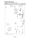
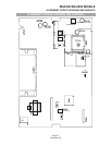
5. On the main board adjust RV103 until the squelch is just unmuted (open)
6. Switch off the RF generator (squelch should close).
7. Switch on the RF generator. Squelch should open at the SINAD point where RV103 was adjusted.
This completes the narrow band adjustment.
8. Select a receiver channel that is programmed for wide band operation (25 kHz).
9. Set the RF signal generator to the receiver frequency. Set the AF modulation signal to 1 kHz at 3k
deviation.
10. Adjust the RF output level of the RF signal generator until the 1 kHz signal is heard.
11. Adjust the RF signal to the level desired for squelch sensitivity as you monitor SINAD. This is
usually 8dB to 12dB SINAD.
12. On the main board adjust RV102 until the squelch is just unmuted (open).
13. Switch off the RF generator (squelch should close).
14. Switch on the RF generator. Squelch should open at the SINAD point where RV102 was
adjusted.
15. Disconnect the test equipment.
Automatic Power Adjustment
•
Continuous transmit periods longer than 5 minutes are to be avoided.
1. Connect the antenna output to a RF power meter or service monitor.
2. Set the PTT switch to the ON position.
3. Adjust the variable resistor RV104 to give the appropriate transmit power. Normally this is
25watts.
4. Set the PTT switch to the OFF position.
5. Select a channel programmed to low transmit power.
6. Set PTT to ON and adjust RV105 for desired low power.
7. Set PTT to OFF.
MAXON SM-2000 MOBILE
SM-2150/VHF ALIGNMENT PROCEDURE
Page-24-
December 98