


Out of Lock Detector
The out-of-lock detector produces a high logic level when Fr and Fv are in the same phase and frequency,
low logic level pulses when the loop is out-of-lock at Pin 2 of IC101. The signals at Pin 2 of IC101 are
buffered by Q106 and then integrating by R114 and C122. The product of the integrating circuit is fed to
L/D port.
Prescaler
The internal Prescaler of IC101 divides the incoming signal frequency from the VCO via input pin 1 by 64
or 65. The divided VCO frequency is passed to the 6-stage A counter and 12-stage N counter.
Receiver
The receiver uses Dual Conversion Superheterodyning techniques, it is comprised of:
1. RF amplifier
2. First Mixer and First IF Amplifier
3. Second Mixer, Second IF Amplifier and FM Detector
4. Receiver Audio Circuit
5. Mute (squelch) Circuit
RF Amplifier
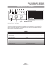
The signal received via the antenna is routed through the 9th chebyshev low-pass filters containing
capacitors C273, C275, C277, C280, C283 and coils L128, L130, L131, L132, and is passed through the
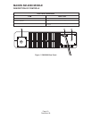
front-end module (RF amplifier) via pin 1. The front-end module contains L800 to L806 and Q800. The
front-end module is configured to enable the RF signal at the operating frequency to pass the first mixer.
First Mixer and First IF Amplifier
The VCO local oscillator signal routed through buffer transistor Q113 and Q114 is filtered by C164, C165,
C281, C310, and L110, L123. IC102 produces a difference frequency IF of 45MHz from pin 6 of the
front-end module and the filtered VCO local oscillator signal at pin 1. The 45MHz difference frequency is
filtered by the 2-pole crystal filter CF101. The tuned circuit T101 and T102 and associated components
provide matching of the crystal filter to insure good band-pass response and selectivity. The IF signal is
amplified by Q130 and passed to the second mixer, second IF and FM detector IC109.
Second Mixer, Second IF and FM Detector
A signal conversion FM receiver integrated chip, IC109 contains the second mixer, second IF and FM
detector functions. The second local oscillator frequency is determined by the crystal X101 connected to
pin 1 of IC109. The IF signal is received at pin 16 of IC109 via R203 and coupling capacitor C182. The
second IF frequency of 455kHz is produced when the different frequency is applied to the mixer via Pin 6.
The output of the second mixer via Pin 3 is applied to a 455kHz band-pass filter, CF104 for 25kHz and
CF103 for 12.5kHz channel spacing. The output of CF104 is passed to a high gain IF amplifier (limiter) in
IC109 via Pin 5. The amplified signal is coupled to the adjustable quadrature detector T103. Any detected
signal is produced at Pin 9 of IC109 and applied to the Receiver Audio Circuit and the Mute (Squelch)
Circuit.
MAXON SM-2000 MOBILE
THEORY OF OPERATION
Page-16-
December 98